Rev. 1.60 68 August 20, 2019 Rev. 1.60 69 August 20, 2019
BS66F340/BS66F350/BS66F360/BS66F370
Touch A/D Flash MCU with LED Driver
BS66F340/BS66F350/BS66F360/BS66F370
Touch A/D Flash MCU with LED Driver
HXT
Prescaler
f
H
LXT
High Speed
Oscillators
f
H
/2
f
H
/16
f
H
/64
f
H
/8
f
H
/4
f
H
/32
CKS2~CKS0
f
SYS
f
SUB
f
SUB
HXTEN
FSS
LIRC
LXTEN
f
LIRC
f
LIRC
HIRC
HIRCEN
f
H
FHS
Low Speed
Oscillators
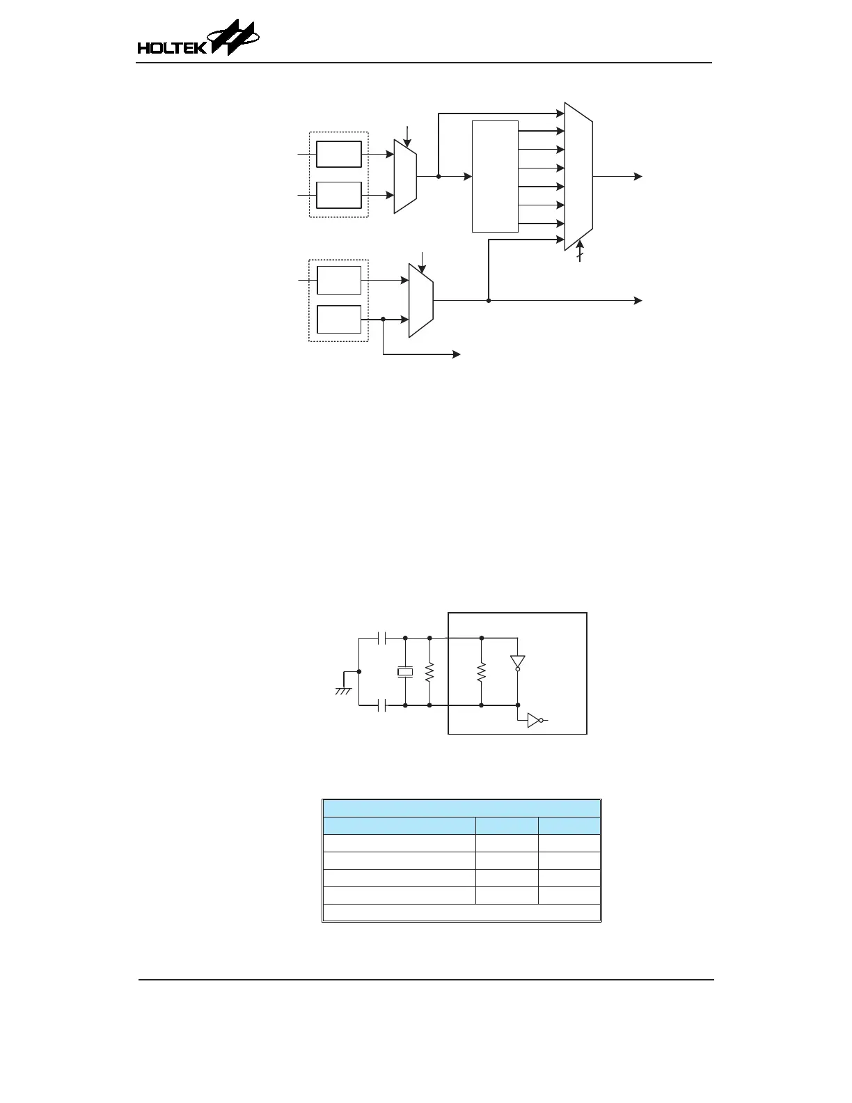
System Clock Congurations
External Crystal/Ceramic Oscillator – HXT
The External Crystal/Ceramic System Oscillator is the high frequency oscillator, which is the
default oscillator clock source after power on. For most crystal oscillator congurations, the simple
connection of a crystal across OSC1 and OSC2 will create the necessary phase shift and feedback for
oscillation, without requiring external capacitors. However, for some crystal types and frequencies,
to ensure oscillation, it may be necessary to add two small value capacitors, C1 and C2. Using a
ceramic resonator will usually require two small value capacitors, C1 and C2, to be connected as
shown for oscillation to occur. The values of C1 and C2 should be selected in consultation with the
crystal or resonator manufacturer’s specication.
For oscillator stability and to minimise the effects of noise and crosstalk, it is important to ensure
that the crystal and any associated resistors and capacitors along with interconnecting lines are all
located as close to the MCU as possible.
Crystal/Resonator Oscillator
HXT Oscillator C1 and C2 Values
Crystal Frequency C1 C2
12MHz 0 pF 0 pF
8MHz 0 pF 0 pF
4MHz 0 pF 0 pF
1MHz 100 pF 100 pF
Note
: C1 and C2 values are for guidance only.
Crystal Recommended Capacitor Values