Rev. 1.60 38 August 20, 2019 Rev. 1.60 39 August 20, 2019
BS66F340/BS66F350/BS66F360/BS66F370
Touch A/D Flash MCU with LED Driver
BS66F340/BS66F350/BS66F360/BS66F370
Touch A/D Flash MCU with LED Driver
Look-up Table
Any location within the Program Memory can be dened as a look-up table where programmers can
store xed data. To use the look-up table, the table pointer must rst be setup by placing the address
of the look up data to be retrieved in the table pointer register, TBLP and TBHP. These registers
dene the total address of the look-up table.
After setting up the table pointer, the table data can be retrieved from the Program Memory using
the "TABRD [m]" or "TABRDL [m]" instructions respectively when the memory [m] is located in
sector 0. If the memory [m] is located in other sectors except sector 0, the data can be retrieved from
the program memory using the corresponding extended table read instruction such as "LTABRD [m]"
or "LTABRDL [m]" respectively. When the instruction is executed, the lower order table byte from
the Program Memory will be transferred to the user dened Data Memory register [m] as specied
in the instruction. The higher order table data byte from the Program Memory will be transferred to
the TBLH special register. Any unused bits in this transferred higher order byte will be read as "0".
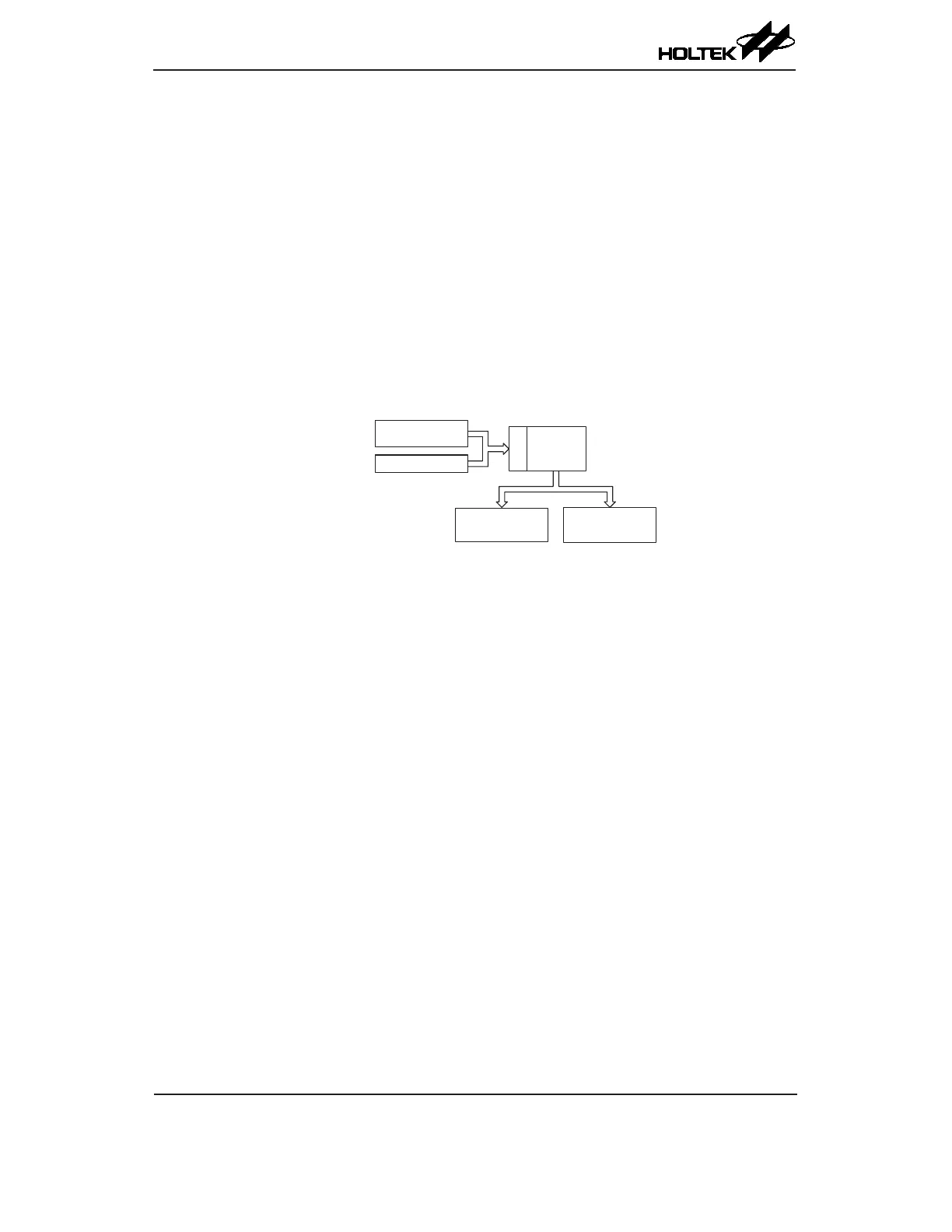
The accompanying diagram illustrates the addressing data ow of the look-up table.
Register T BLH
User S electe d
Register
TBLP R egis te r
Data
Address
16 b its
Last p age o r
TBHP R egister
Table Program Example
The accompanying example shows how the table pointer and table data is defined and retrieved
from the device. This example uses raw table data located in the last page which is stored there
using the ORG statement. The value at this ORG statement is "0F00H" which refers to the start
address of the last page within the 4K Program Memory of the BS66F340 device. The table pointer
low byte register is setup here to have an initial value of "06H". This will ensure that the rst data
read from the data table will be at the Program Memory address "0F06H" or 6 locations after the
start of the last page. Note that the value for the table pointer is referenced to the rst address of the
present page pointed by the TBHP register if the "TABRD [m]" instruction is being used. The high
byte of the table data which in this case is equal to zero will be transferred to the TBLH register
automatically when the "TABRD [m] instruction is executed.
Because the TBLH register is a read/write register and can be restored, care should be taken
to ensure its protection if both the main routine and Interrupt Service Routine use table read
instructions. If using the table read instructions, the Interrupt Service Routines may change the
value of the TBLH and subsequently cause errors if used again by the main routine. As a rule it is
recommended that simultaneous use of the table read instructions should be avoided. However, in
situations where simultaneous use cannot be avoided, the interrupts should be disabled prior to the
execution of any main routine table-read instructions. Note that all table related instructions require
two instruction cycles to complete their operation.