Rev. 1.60 72 August 20, 2019 Rev. 1.60 73 August 20, 2019
BS66F340/BS66F350/BS66F360/BS66F370
Touch A/D Flash MCU with LED Driver
BS66F340/BS66F350/BS66F360/BS66F370
Touch A/D Flash MCU with LED Driver
NORMAL Mode
As the name suggests this is one of the main operating modes where the microcontroller has all of
its functions operational and where the system clock is provided by one of the high speed oscillators.
This mode operates allowing the microcontroller to operate normally with a clock source will come
from one of the high speed oscillators, either the HXT or HIRC oscillators. The high speed oscillator
will however first be divided by a ratio ranging from 1 to 64, the actual ratio being selected by
the CKS2~CKS0 bits in the SCC register.Although a high speed oscillator is used, running the
microcontroller at a divided clock ratio reduces the operating current.
SLOW Mode
This is also a mode where the microcontroller operates normally although now with a slower speed
clock source. The clock source used will be from f
SUB
. The f
SUB
clock is derived from either the
LIRC or LXT oscillator.
SLEEP Mode
The SLEEP Mode is entered when a HALT instruction is executed and when the FHIDEN and
FSIDEN bit are low. In the SLEEP mode the CPU will be stopped. However the f
LIRC
clock still
continues to operate since the WDT function is always enabled.
IDLE0 Mode
The IDLE0 Mode is entered when a HALT instruction is executed and when the FHIDEN bit in
the SCC register is low and the FSIDEN bit in the SCC register is high. In the IDLE0 Mode the
CPU will be switched off but the low speed oscillator will be turned on to drive some peripheral
functions.
IDLE1 Mode
The IDLE1 Mode is entered when a HALT instruction is executed and when the FHIDEN bit in the
SCC register is high and the FSIDEN bit in the SCC register is high. In the IDLE1 Mode the CPU
will be switched off but both the high and low speed oscillators will be turned on to provide a clock
source to keep some peripheral functions operational.
IDLE2 Mode
The IDLE2 Mode is entered when a HALT instruction is executed and when the FHIDEN bit in the
SCC register is high and the FSIDEN bit in the SCC register is low. In the IDLE2 Mode the CPU
will be switched off but the high speed oscillator will be turned on to provide a clock source to keep
some peripheral functions operational.
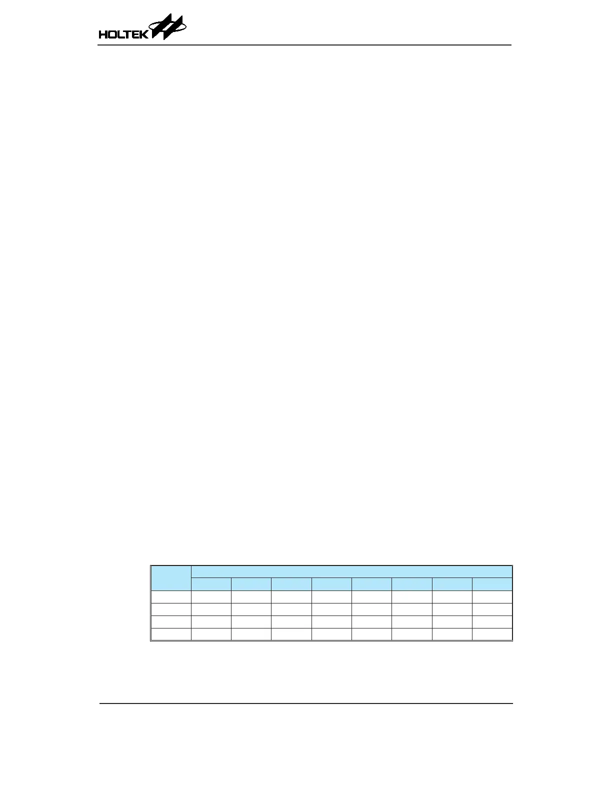
Control Registers
The registers, SCC, HIRCC, HXTC and LXTC, are used to control the system clock and the
corresponding oscillator congurations.
Register
Name
Bit
7 6 5 4 3 2 1 0
SCC CKS2 CKS1 CKS0 — FHS FSS FHIDEN FSIDEN
HIRCC — — — — HIRC1 HIRC0 HIRCF HIRCEN
HXTC — — — — — HXTM HXTF HXTEN
LXTC — — — — — LXTSP LXTF LXTEN
System Operating Mode Control Registers List