Rev. 1.60 108 August 20, 2019 Rev. 1.60 109 August 20, 2019
BS66F340/BS66F350/BS66F360/BS66F370
Touch A/D Flash MCU with LED Driver
BS66F340/BS66F350/BS66F360/BS66F370
Touch A/D Flash MCU with LED Driver
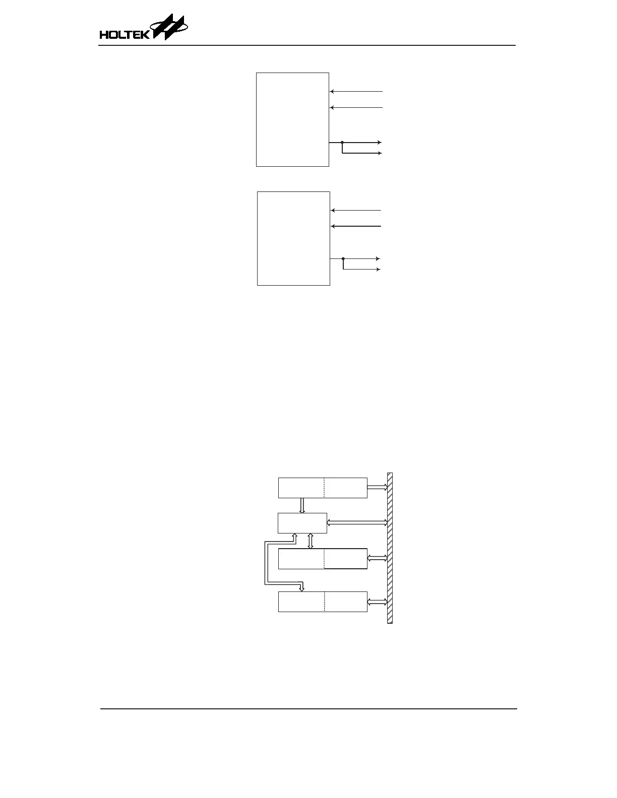
STM
STCK
STP
STPI
CCR capture input
CCR output
STPB
STM Function Pin Control Block Diagram
PTM
PTCK
PTP
PTPI
CCR capture input
CCR output
PTPB
PTM Function Pin Control Block Diagram
Programming Considerations
The TM Counter Registers and the Capture/Compare CCRA and CCRP registers, all have a low and
high byte structure. The high bytes can be directly accessed, but as the low bytes can only be accessed
via an internal 8-bit buffer, reading or writing to these register pairs must be carried out in a specic
way. The important point to note is that data transfer to and from the 8-bit buffer and its related low
byte only takes place when a write or read operation to its corresponding high byte is executed.
As the CCRA and CCRP registers are implemented in the way shown in the following diagram and
accessing these register pairs is carried out in a specic way as described above, it is recommended
to use the "MOV" instruction to access the CCRA and CCRP low byte registers, named xTMnAL
and PTMRPL, using the following access procedures. Accessing the CCRA or CCRB low byte
registers without following these access procedures will result in unpredictable values.
Data Bus
8-bit Buffer
xTMnAH
xTMnAL
xTMn Counter Register (Read only)
xTMn CCRA Register (Read/Write)
PTMRPHPTMRPL
PTM CCRP Register (Read/Write)
xTMnDHxTMnDL
The following steps show the read and write procedures:
• Writing Data to CCRA or CCRP
♦
Step 1. Write data to Low Byte xTMnAL or PTMRPL
– note that here data is only written to the 8-bit buffer.