Rev. 1.60 202 August 20, 2019 Rev. 1.60 203 August 20, 2019
BS66F340/BS66F350/BS66F360/BS66F370
Touch A/D Flash MCU with LED Driver
BS66F340/BS66F350/BS66F360/BS66F370
Touch A/D Flash MCU with LED Driver
Interrupts
Interrupts are an important part of any microcontroller system. When an external event or an
internal function such as a Timer Module or an A/D converter requires microcontroller attention,
their corresponding interrupt will enforce a temporary suspension of the main program allowing the
microcontroller to direct attention to their respective needs. These devices contain several external
interrupt and internal interrupts functions. The external interrupts are generated by the action of
the external INT0 and INT1 pins, while the internal interrupts are generated by various internal
functions such as the TMs, Touch Key, Time Base, LVD, EEPROM, SIM, UART and the A/D
converter, etc.
Interrupt Registers
Overall interrupt control, which basically means the setting of request flags when certain
microcontroller conditions occur and the setting of interrupt enable bits by the application program,
is controlled by a series of registers, located in the Special Purpose Data Memory, as shown in the
accompanying table. The number of registers depends upon the device chosen but fall into three
categories. The rst is the INTC0~INTC2 registers which setup the primary interrupts, the second
is the MFI0~MFI3 registers which setup the Multi-function interrupts. Finally there is an INTEG
register to setup the external interrupt trigger edge type.
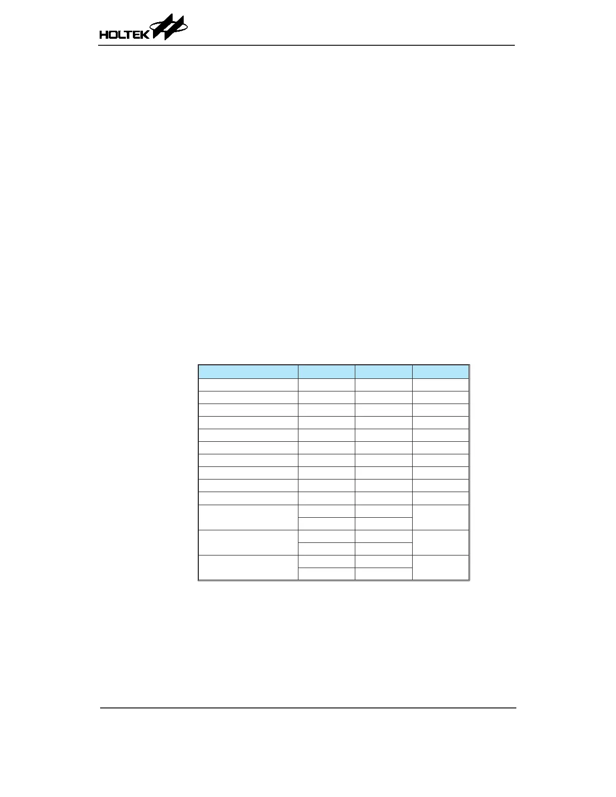
Each register contains a number of enable bits to enable or disable individual interrupts as well
as interrupt ags to indicate the presence of an interrupt request. The naming convention of these
follows a specic pattern. First is listed an abbreviated interrupt type, then the (optional) number of
that interrupt followed by either an "E" for enable/disable bit or "F" for request ag.
Function Enable Bit Request Flag Notes
Global EMI — —
INTn Pins INTnE INTnF n=0~1
Touch Key TKME TKMF —
UART URE URF —
Multi-function MFnE MFnF n=0~3
A/D Converter ADE ADF —
Time Base TBnE TBnF n=0~1
LVD LVE LVF —
EEPROM write operation DEE DEF —
SIM SIME SIMF —
CTM
CTMnPE CTMnPF
n=0~1
CTMnAE CTMnAF
PTM
PTMPE PTMPF
—
PTMAE PTMAF
STM
STMPE STMPF
—
STMAE STMAF
Interrupt Register Bit Naming Conventions