Rev. 1.60 186 August 20, 2019 Rev. 1.60 187 August 20, 2019
BS66F340/BS66F350/BS66F360/BS66F370
Touch A/D Flash MCU with LED Driver
BS66F340/BS66F350/BS66F360/BS66F370
Touch A/D Flash MCU with LED Driver
Touch Key Function
Each device provides multiple touch key functions. The touch key function is fully integrated and
requires no external components, allowing touch key functions to be implemented by the simple
manipulation of internal registers.
Touch Key Structure
The touch keys are pin shared with the I/O pins, with the desired function chosen via the pin-shared
selection register bit. Keys are organised into several groups, with each group known as a module
and having a module number, M0 to Mn. Each module is a fully independent set of four Touch Keys
and each Touch Key has its own oscillator. Each module contains its own control logic circuits and
register set. Examination of the register names will reveal the module number it is referring to.
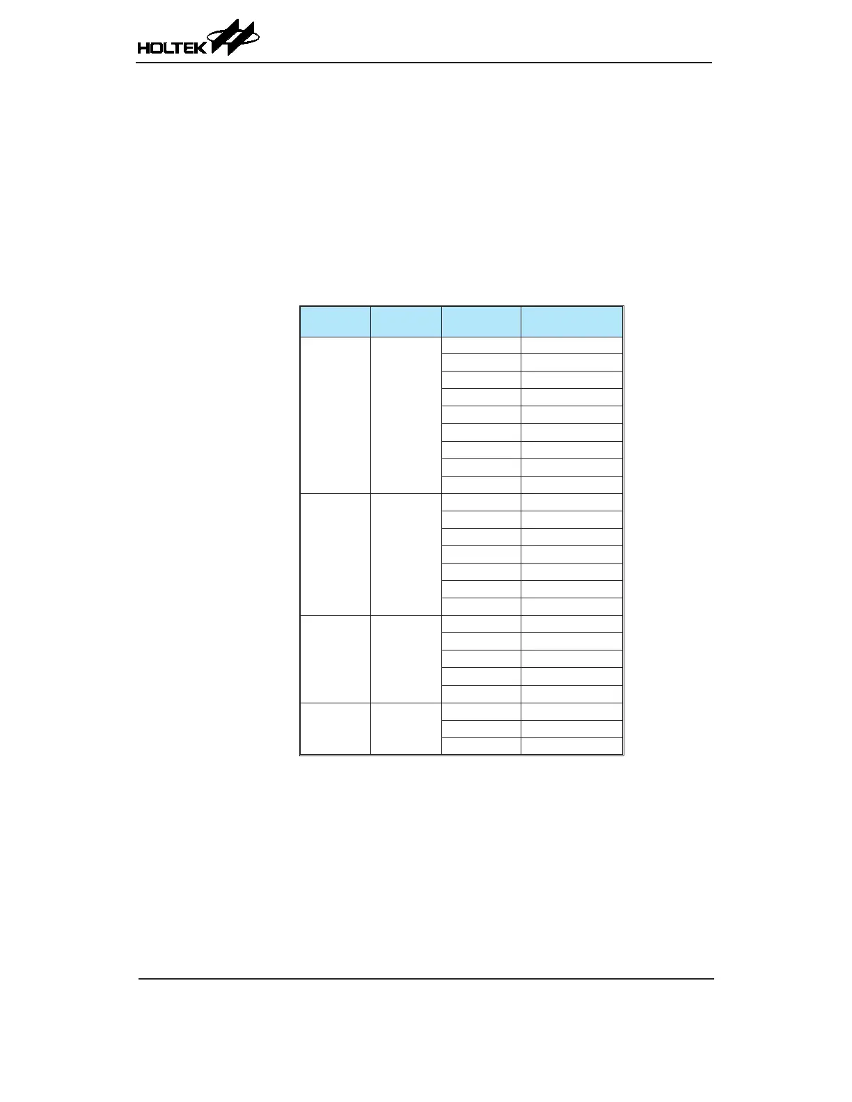
Device
Total Key
Number
Touch Key
Module
Touch Key
BS66F370 36
M0 KEY1~KEY4
M1 KEY5~KEY8
M2 KEY9~KEY12
M3 KEY13~KEY16
M4 KEY17~KEY20
M5 KEY21~KEY24
M6 KEY25~KEY28
M7 KEY29~KEY32
M8 KEY33~KEY36
BS66F360 28
M0 KEY1~KEY4
M1 KEY5~KEY8
M2 KEY9~KEY12
M3 KEY13~KEY16
M4 KEY17~KEY20
M5 KEY21~KEY24
M6 KEY25~KEY28
BS66F350 20
M0 KEY1~KEY4
M1 KEY5~KEY8
M2 KEY9~KEY12
M3 KEY13~KEY16
M4 KEY17~KEY20
BS66F340 12
M0 KEY1~KEY4
M1 KEY5~KEY8
M2 KEY9~KEY12
Touch Key Structure