Rev. 1.60 84 August 20, 2019 Rev. 1.60 85 August 20, 2019
BS66F340/BS66F350/BS66F360/BS66F370
Touch A/D Flash MCU with LED Driver
BS66F340/BS66F350/BS66F360/BS66F370
Touch A/D Flash MCU with LED Driver
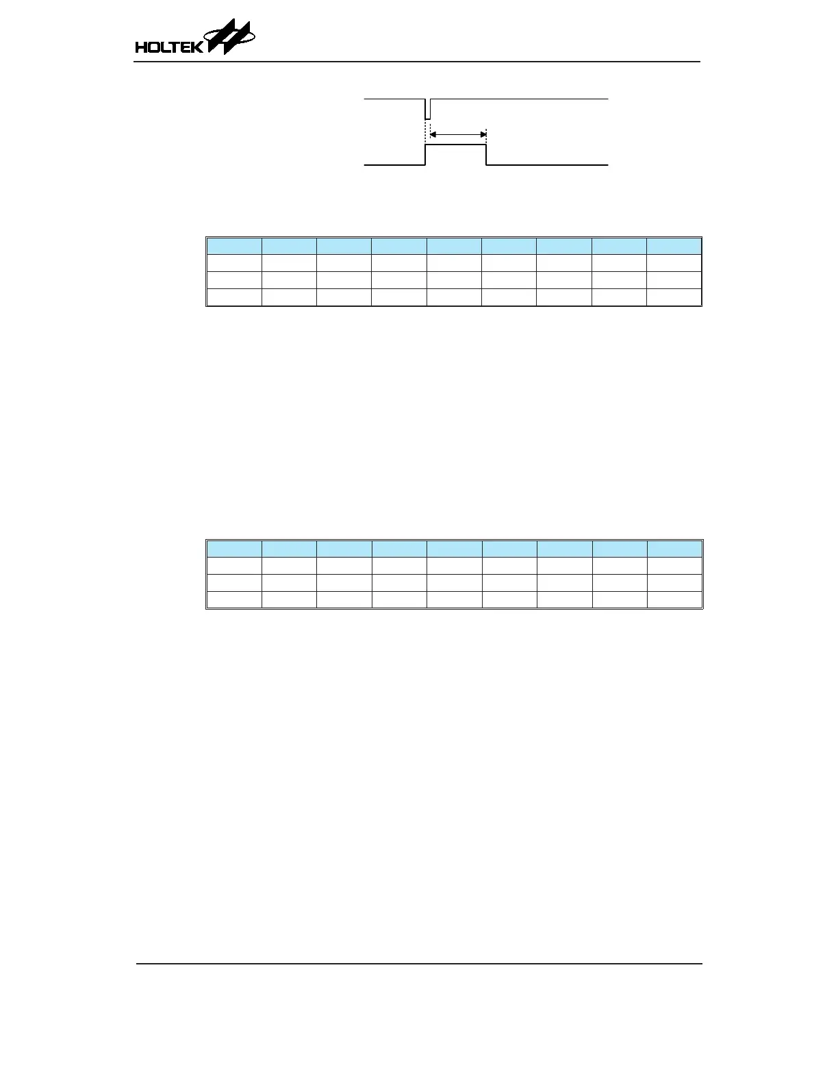
LVR
Internal Reset
t
RSTD
+ t
SST
Note: t
RSTD
is power-on delay with typical time=50ms
Low Voltage Reset Timing Chart
• LVRC Register
Bit 7 6 5 4 3 2 1 0
Name LVS7 LVS6 LVS5 LVS4 LVS3 LVS2 LVS1 LVS0
R/W R/W R/W R/W R/W R/W R/W R/W R/W
POR 0 1 0 1 0 1 0 1
Bit 7~0 LVS7~LVS0: LVR voltage select
01010101: 2.1V
00110011: 2.55V
10011001: 3.15V
10101010: 3.8V
Other values: Generates a MCU reset – register is reset to POR value
When an actual low voltage condition occurs, as specied by one of the four dened
LVR voltage value above, an MCU reset will generated. The reset operation will be
activated after 2~3 f
LIRC
clock cycles. In this situation the register contents will remain
the same after such a reset occurs.
Any register value, other than the four dened register values above, will also result in
the generation of an MCU reset. The reset operation will be activated after 2~3 f
LIRC
clock
cycles. However in this situation the register contents will be reset to the POR value.
• RSTFC Register
Bit 7 6 5 4 3 2 1 0
Name — — — — RSTF LVRF LRF WRF
R/W — — — — R/W R/W R/W R/W
POR — — — — 0 x 0 0
"x": unknown
Bit 7~4 Unimplemented, read as "0"
Bit 3 RSTF: Reset control register software reset ag
Described elsewhere.
Bit 2 LVRF: LVR function reset ag
0: Not occurred
1: Occurred
This bit is set to 1 when a specic low voltage reset condition occurs. Note that this bit
can only be cleared to 0 by the application program.
Bit 1 LRF: LVR control register software reset ag
0: Not occurred
1: Occurred
This bit is set to 1 by the LVRC control register contains any undened LVR voltage
register values. This in effect acts like a software-reset function. Note that this bit can
only be cleared to 0 by the application program.
Bit 0 WRF: WDT control register software reset ag
Described elsewhere.