Rev. 1.60 114 August 20, 2019 Rev. 1.60 115 August 20, 2019
BS66F340/BS66F350/BS66F360/BS66F370
Touch A/D Flash MCU with LED Driver
BS66F340/BS66F350/BS66F360/BS66F370
Touch A/D Flash MCU with LED Driver
the CTMn output pin. The way in which the CTMn output pin changes state are determined by
the condition of the CTnIO1 and CTnIO0 bits in the CTMnC1 register. The CTMn output pin can
be selected using the CTnIO1 and CTnIO0 bits to go high, to go low or to toggle from its present
condition when a compare match occurs from Comparator A. The initial condition of the CTMn
output pin, which is setup after the CTnON bit changes from low to high, is setup using the CTnOC
bit. Note that if the CTnIO1 and CTnIO0 bits are zero then no pin change will take place.
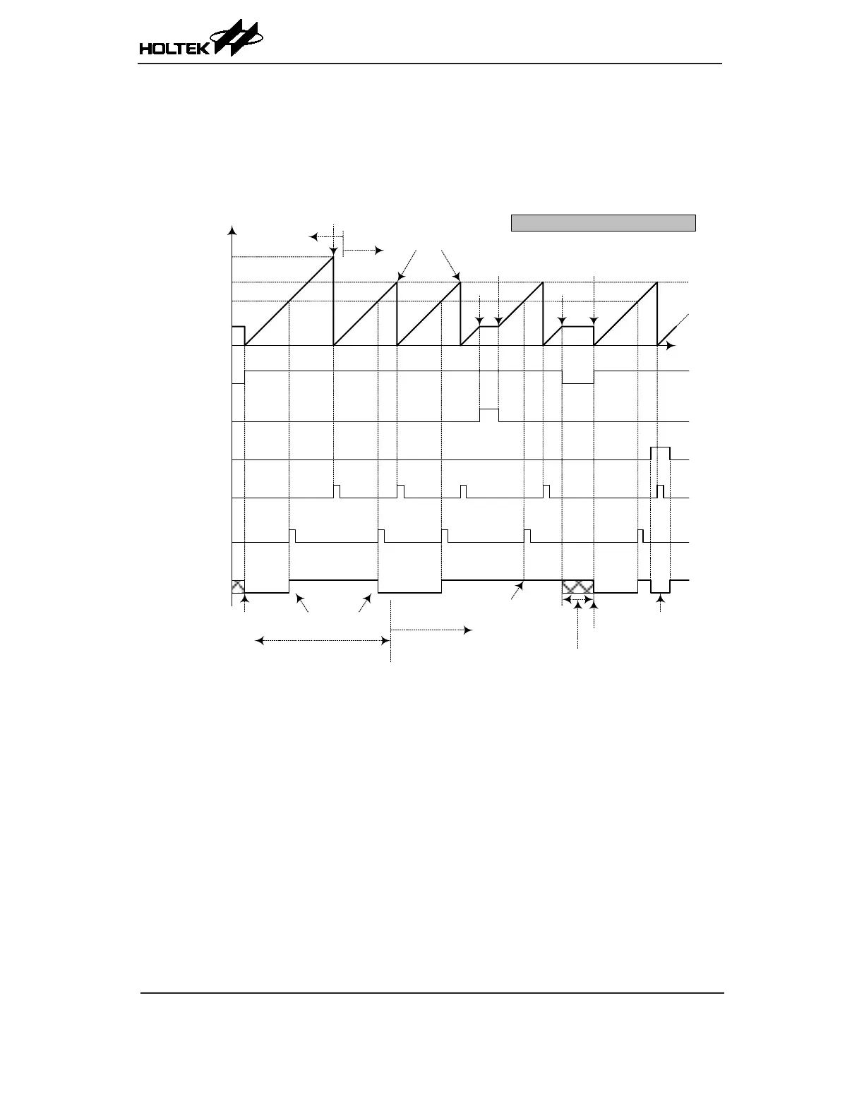
Counter Value
0x3FF
CCRP
CCRA
CTnON
CTnPAU
CTnPOL
CCRP Int.
flag CTMnPF
CCRA Int.
flag CTMnAF
CTMn O/P Pin
Time
CCRP=0
CCRP > 0
Counter overflow
CCRP > 0
Counter cleared by CCRP value
Pause
Resume
Stop
Counter
Restart
CTnCCLR = 0; CTnM [1:0] = 00
Output pin set to
initial Level Low
if CTnOC=0
Output Toggle with
CTMnAF flag
Note CTnIO [1:0] = 10
Active High Output select
Here CTnIO [1:0] = 11
Toggle Output select
Output not affected by CTMnAF
flag. Remains High until reset by
CTnON bit
Output Pin
Reset to Initial value
Output controlled by
other pin-shared function
Output Inverts
when CTnPOL is high
Compare Match Output Mode – CTnCCLR=0
Note: 1. With CTnCCLR=0, a Comparator P match will clear the counter
2. The CTMn output pin controlled only by CTMnAF ag
3. The output pin is reset to its initial state by CTnON bit rising edge
4. n=0 or 1