Rev. 1.60 120 August 20, 2019 Rev. 1.60 121 August 20, 2019
BS66F340/BS66F350/BS66F360/BS66F370
Touch A/D Flash MCU with LED Driver
BS66F340/BS66F350/BS66F360/BS66F370
Touch A/D Flash MCU with LED Driver
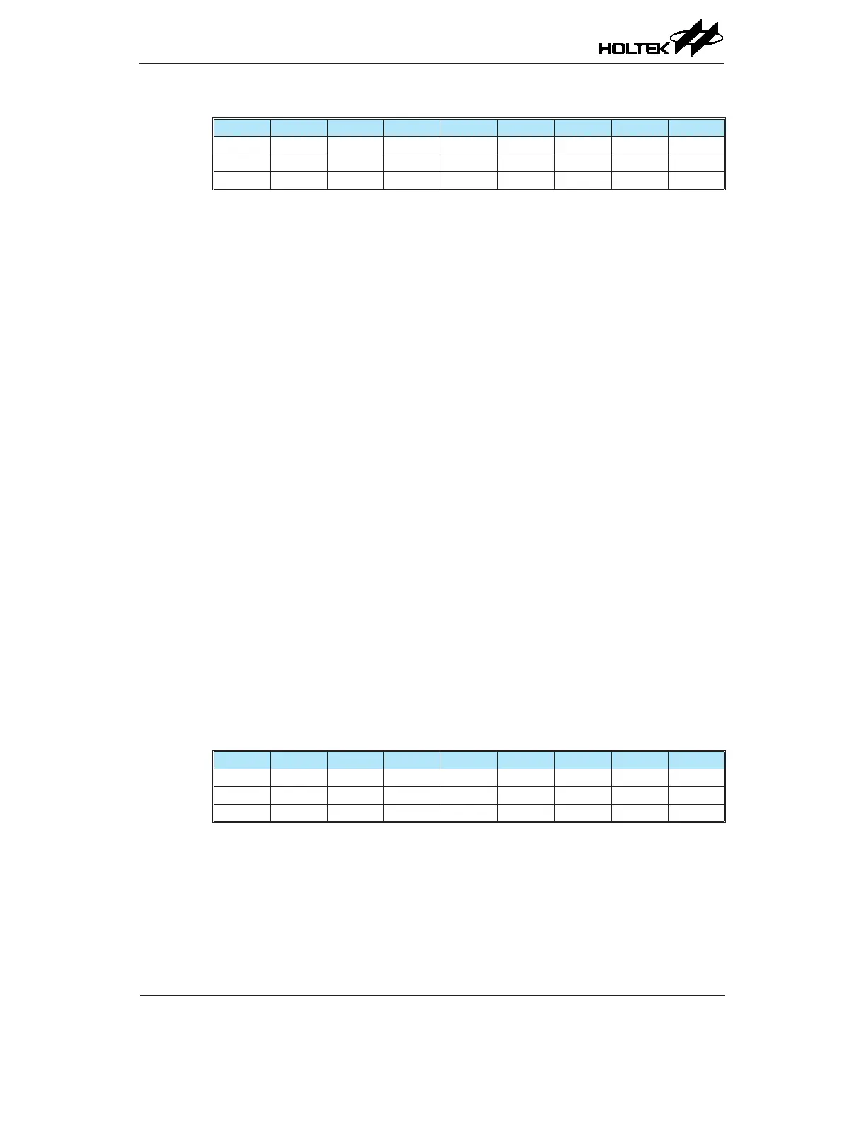
• STMC0 Register
Bit 7 6 5 4 3 2 1 0
Name STPAU STCK2 STCK1 STCK0 STON — — —
R/W R/W R/W R/W R/W R/W — — —
POR 0 0 0 0 0 — — —
Bit 7 STPAU: STM Counter Pause control
0: Run
1: Pause
The counter can be paused by setting this bit high. Clearing the bit to zero restores
normal counter operation. When in a Pause condition the STM will remain powered
up and continue to consume power. The counter will retain its residual value when
this bit changes from low to high and resume counting from this value when the bit
changes to a low value again.
Bit 6~4 STCK2~STCK0: Select STM Counter clock
000: f
SYS
/4
001: f
SYS
010: f
H
/16
011: f
H
/64
100: f
SUB
101: f
SUB
110: STCK rising edge clock
111: STCK falling edge clock
These three bits are used to select the clock source for the STM. The external pin clock
source can be chosen to be active on the rising or falling edge. The clock source f
SYS
is
the system clock, while f
H
and f
SUB
are other internal clocks, the details of which can
be found in the oscillator section.
Bit 3 STON: STM Counter On/Off control
0: Off
1: On
This bit controls the overall on/off function of the STM. Setting the bit high enables
the counter to run while clearing the bit disables the STM. Clearing this bit to zero
will stop the counter from counting and turn off the STM which will reduce its power
consumption. When the bit changes state from low to high the internal counter value
will be reset to zero, however when the bit changes from high to low, the internal
counter will retain its residual value until the bit returns high again. If the STM is in
the Compare Match Output Mode then the STM output pin will be reset to its initial
condition, as specied by the STOC bit, when the STON bit changes from low to high.
Bit 2~0 Unimplemented, read as "0"
• STMC1 Register
Bit 7 6 5 4 3 2 1 0
Name STM1 STM0 STIO1 STIO0 STOC STPOL STDPX STCCLR
R/W R/W R/W R/W R/W R/W R/W R/W R/W
POR 0 0 0 0 0 0 0 0
Bit 7~6 STM1~STM0: Select STM Operating Mode
00: Compare Match Output Mode
01: Capture Input Mode
10: PWM Mode or Single Pulse Output Mode
11: Timer/Counter Mode
These bits setup the required operating mode for the STM. To ensure reliable operation
the STM should be switched off before any changes are made to the STM1 and STM0
bits. In the Timer/Counter Mode, the STM output pin control will be disabled.