Rev. 1.60 134 August 20, 2019 Rev. 1.60 135 August 20, 2019
BS66F340/BS66F350/BS66F360/BS66F370
Touch A/D Flash MCU with LED Driver
BS66F340/BS66F350/BS66F360/BS66F370
Touch A/D Flash MCU with LED Driver
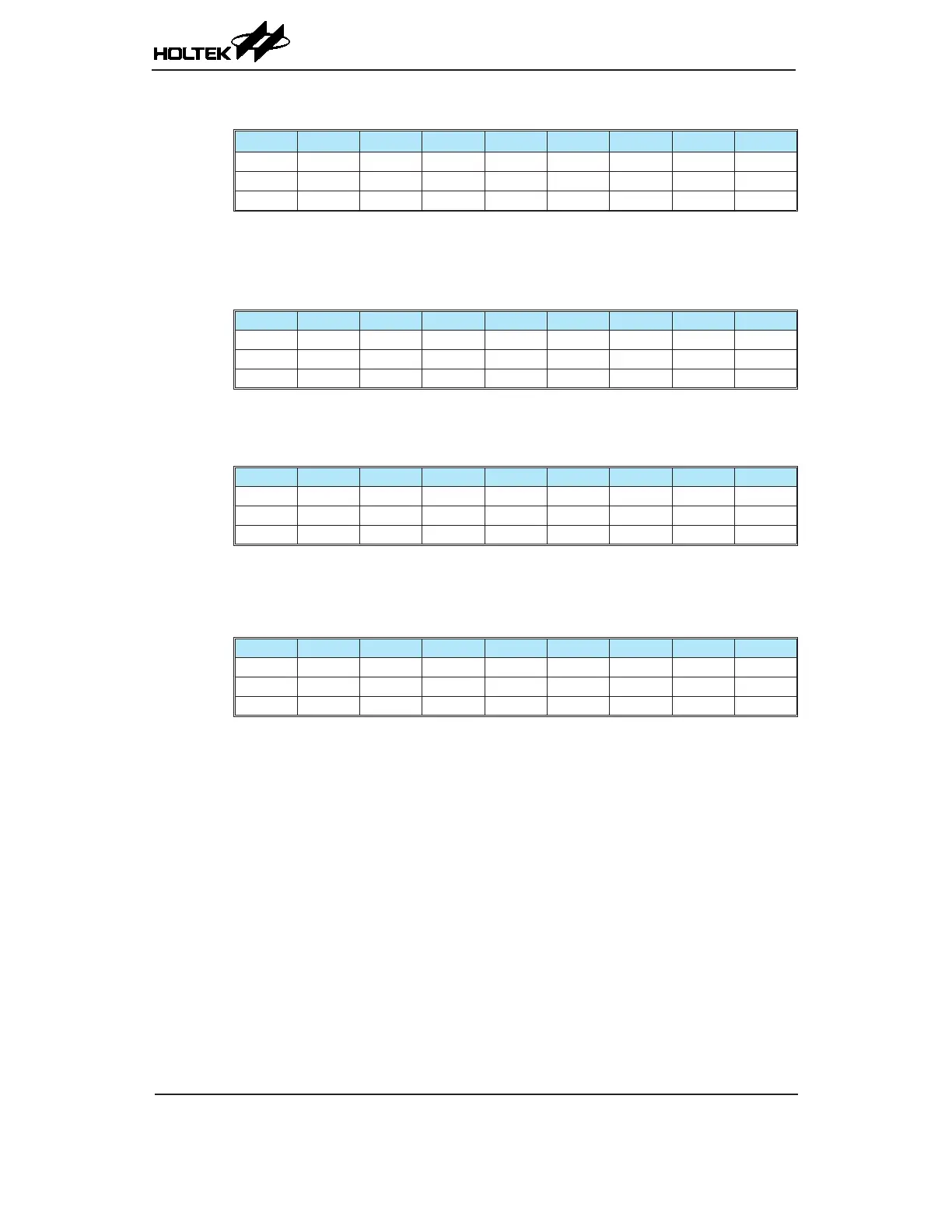
• PTMAH Register
Bit 7 6 5 4 3 2 1 0
Name — — — — — — D9 D8
R/W — — — — — — R/W R/W
POR — — — — — — 0 0
Bit 7~2 Unimplemented, read as "0"
Bit 1~0 PTM CCRA High Byte Register bit 1 ~ bit 0
PTM 10-bit CCRA bit 9 ~ bit 8
• PTMRPL Register
Bit 7 6 5 4 3 2 1 0
Name PTRP7 PTRP6 PTRP5 PTRP4 PTRP3 PTRP2 PTRP1 PTRP0
R/W R/W R/W R/W R/W R/W R/W R/W R/W
POR 0 0 0 0 0 0 0 0
Bit 7~0 PTRP7~PTRP0: PTM CCRP Low Byte Register bit 7 ~ bit 0
PTM 10-bit CCRP bit 7 ~ bit 0
• PTMRPH Register
Bit 7 6 5 4 3 2 1 0
Name — — — — — — PTRP9 PTRP8
R/W — — — — — — R/W R/W
POR — — — — — — 0 0
Bit 7~2 Unimplemented, read as "0"
Bit 1~0 PTRP9~PTRP8: PTM CCRP High Byte Register bit 1 ~ bit 0
PTM 10-bit CCRP bit 9 ~ bit 8
• PTMC0 Register
Bit 7 6 5 4 3 2 1 0
Name PTPAU PTCK2 PTCK1 PTCK0 PTON — — —
R/W R/W R/W R/W R/W R/W — — —
POR 0 0 0 0 0 — — —
Bit 7 PTPAU: PTM Counter Pause control
0: Run
1: Pause
The counter can be paused by setting this bit high. Clearing the bit to zero restores
normal counter operation. When in a Pause condition the PTM will remain powered
up and continue to consume power. The counter will retain its residual value when
this bit changes from low to high and resume counting from this value when the bit
changes to a low value again.
Bit 6~4 PTCK2~PTCK0: Select PTM Counter clock
000: f
SYS
/4
001: f
SYS
010: f
H
/16
011: f
H
/64
100: f
SUB
101: f
SUB
110: PTCK rising edge clock
111: PTCK falling edge clock
These three bits are used to select the clock source for the PTM. The external pin clock
source can be chosen to be active on the rising or falling edge. The clock source f
SYS
is
the system clock, while f
H
and f
SUB
are other internal clocks, the details of which can
be found in the oscillator section.