Rev. 1.60 170 August 20, 2019 Rev. 1.60 171 August 20, 2019
BS66F340/BS66F350/BS66F360/BS66F370
Touch A/D Flash MCU with LED Driver
BS66F340/BS66F350/BS66F360/BS66F370
Touch A/D Flash MCU with LED Driver
I
2
C Time-out Control
In order to reduce the I
2
C lockup problem due to reception of erroneous clock sources, a time-out
function is provided. If the clock source connected to the I
2
C bus is not received for a while, then
the I
2
C circuitry and registers will be reset after a certain time-out period. The time-out counter
starts to count on an I
2
C bus "START" & "address match"condition, and is cleared by an SCL falling
edge. Before the next SCL falling edge arrives, if the time elapsed is greater than the time-out period
specied by the SIMTOC register, then a time-out condition will occur. The time-out function will
stop when an I
2
C "STOP" condition occurs.
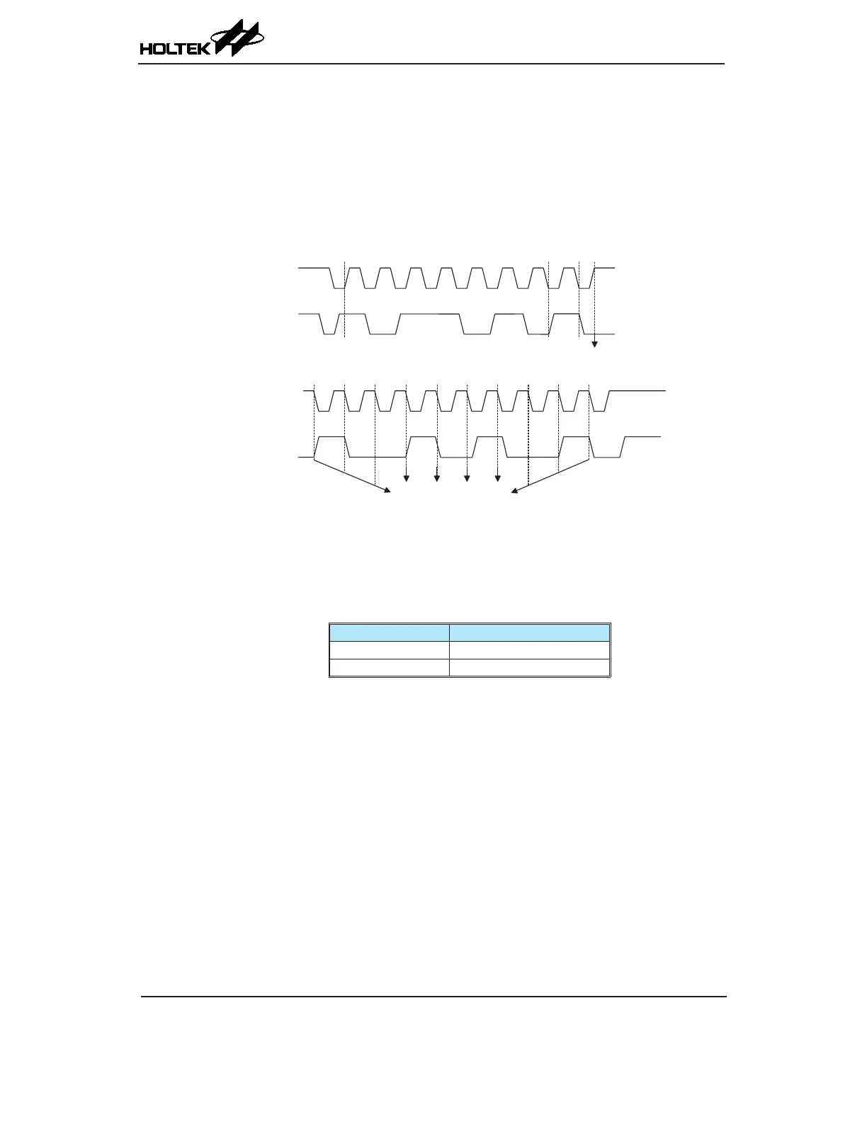
I C time- out
c ounte r start
I C time- out c ounte r re set
on SCL negativ e transitio n
101 001 00
1
0
01010
1
1
L
A
Stop
SCL
A
2
2
I
2
C Time-out
When an I
2
C time-out counter overow occurs, the counter will stop and the SIMTOEN bit will
be cleared to zero and the SIMTOF bit will be set high to indicate that a time-out condition has
occurred. The time-out condition will also generate an interrupt which uses the I
2
C interrrupt vector.
When an I
2
C time-out occurs, the I
2
C internal circuitry will be reset and the registers will be reset
into the following condition:
Register After I
2
C Time-out
SIMD, SIMA, SIMC0 No change
SIMC1 Reset to POR condition
I
2
C Register after Time-out
The SIMTOF ag can be cleared by the application program. There are 64 time-out period selections
which can be selected using the SIMTOS bits in the SIMTOC register. The time-out duration is
calculated by the formula: ((1~64) × (32/f
SUB
)). This gives a time-out period which ranges from
about 1ms to 64ms.