Rev. 1.60 46 August 20, 2019 Rev. 1.60 47 August 20, 2019
BS66F340/BS66F350/BS66F360/BS66F370
Touch A/D Flash MCU with LED Driver
BS66F340/BS66F350/BS66F360/BS66F370
Touch A/D Flash MCU with LED Driver
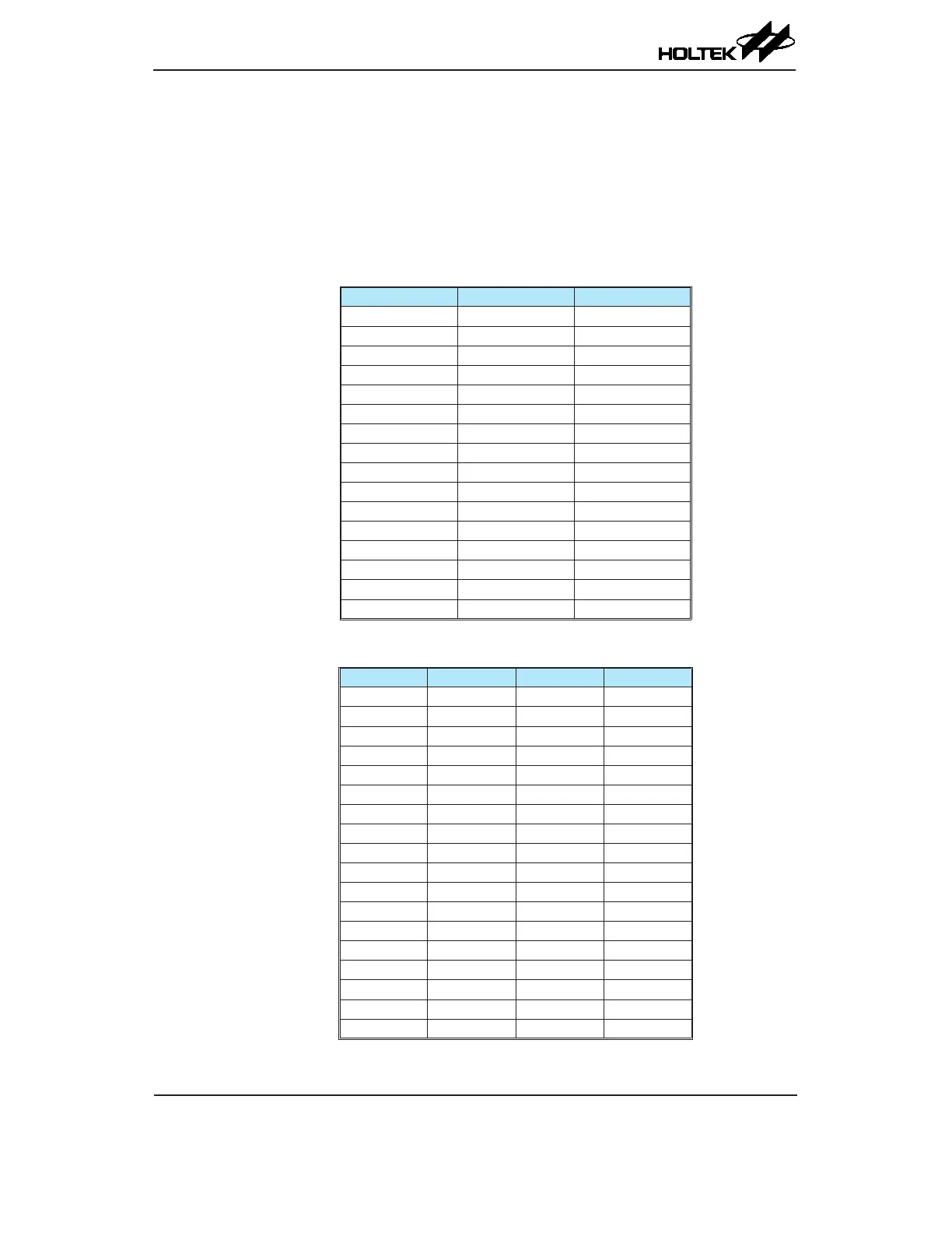
Flash Memory Read/Write Procedure
After the Flash memory write function is successfully enabled through the preceding IAP procedure,
users must first erase the corresponding Flash memory block or page and then initiate the Flash
memory write operation. For the BS66F340 device the number of the block erase operation is
256 words per block, the available block erase address is only specied by FARH register and the
content in the FARL register is not used to specify the block address. For the BS66F350, BS66F360
and BS66F370 devices the number of the page erase operation is 32, 64 and 64 words per page
respectively, the available page erase address is specied by FARH register and the content of FARL
[7:5] and FARL [7:6] bit eld respectively.
Erase Block FARH [3:0] FARL [7:0]
0 0000 xxxx xxxx
1 0001 xxxx xxxx
2 0010 xxxx xxxx
3 0011 xxxx xxxx
4 0100 xxxx xxxx
5 0101 xxxx xxxx
6 0110 xxxx xxxx
7 0111 xxxx xxxx
8 1000 xxxx xxxx
9 1001 xxxx xxxx
10 1010 xxxx xxxx
11 1011 xxxx xxxx
12 1100 xxxx xxxx
13 1101 xxxx xxxx
14 1110 xxxx xxxx
15 1111 xxxx xxxx
"x": don’t care
BS66F340 Erase Block Number and Selection
Erase Page FARH FARL [7:5] FARL [4:0]
0 0000 0000 000 x xxxx
1 0000 0000 001 x xxxx
2 0000 0000 010 x xxxx
3 0000 0000 011 x xxxx
4 0000 0000 100 x xxxx
5 0000 0000 101 x xxxx
6 0000 0000 110 x xxxx
7 0000 0000 111 x xxxx
8 0000 0001 000 x xxxx
9 0000 0001 001 x xxxx
: : : :
126 0000 1111 110 x xxxx
127 0000 1111 111 x xxxx
128 0001 0000 000 x xxxx
129 0001 0000 001 x xxxx
: : : :
254 0001 1111 110 x xxxx
255 0001 1111 111 x xxxx
"x": don’t care
BS66F350 Erase Page Number and Selection