Installation
12 DC1010/1020/1030/1040 Product Manual 8/05
2.6 Wiring Diagrams
2.6.1 Identify Your Wiring Requirements
To determine the appropriate diagrams for wiring your controller, refer to the model
number interpretation in this section. The model number of the controller is on the
outside of the case.
Shielded twisted pair cable are required for all Analog I/O, Process Variable, RTD,
Thermocouple, dc millivolt, low level signal, mA, Digital Output, and computer interface
circuits.
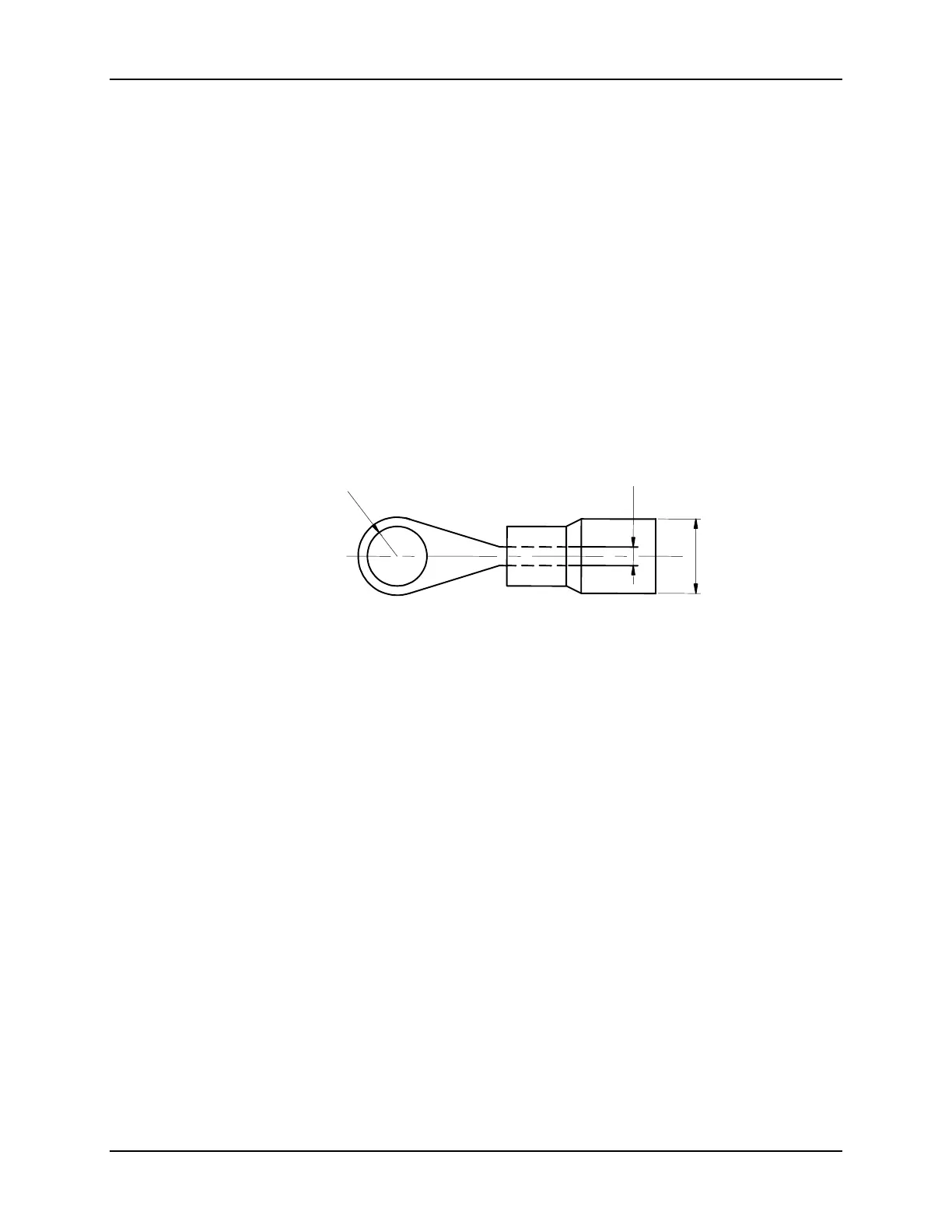
2.6.2 Making Terminal Connections
(1) Connection of power supply input terminal
• Type: Round
• Cable square: 1.25 mm(0.049 in)
• Diameter: 3.0 ~ 3.7 mm(0.118~ 0.145 in)
1.25
5
R1.5
Terminal with tube(R, 1.25 * M3)
• Tighten the terminal screws using a torque between 0.8 N_ m or less.
 Loading...


