Installation
6 DC1010/1020/1030/1040 Product Manual 8/05
2.3 Model Number Interpretation
Introduction
Write your controller’s model number in the spaces provided below and circle the corresponding
items in each table. This information will also be useful when you wire your controller.
Instructions
Select the desired Key Number. The arrow to the right marks the selections available.
Make one selection each from Tables I through III using the column below the proper arrow.
A dot ( ) denotes unrestricted availability. A letter denotes restricted availability.
Key Numbers
DC10_ _ _ _ - _ _ _ - _ _ _ - _
KEY NUMBER
Description Selection
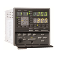
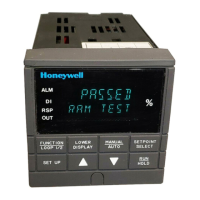
Size 48 x 48 mm (DIN) 1/16) DC1010_ _
48 x 96 mm (DIN 1/8) DC1020_ _
72 x 72 mm DC1030_ _
96 x 96 (DIN 1/4) DC1040_ _
Power 90-240 Vac Power DC10_0_ _
15-50 Vdc Power DC10_1_ _
bbbb
90-240 Vac Power / IP 65 DC10_2_ _
15-50 Vac Power / IP65 DC10_3_ _
bbbb
90-240 Vac Power / UL Agency Approval DC10_4_ _
15-50 Vdc Power / UL Agency Approval DC10_5_ _
bbbb
Program None DC10_ _C_
Program (2 patterns, 8 segments per 1 pattern) DC10_ _P_
Input RTD DC10_ _ _R
TC DC10_ _ _T
Linear DC10_ _ _L
TABLE I
Control Output 1 None 0 _ _
Relay, Contact, SPDT, 3A / 240 VAC 1 _ _
Volt, Voltage Pulse, 20VDC / 20 mA 2 _ _
mA Current, 4-20mA 3 _ _
Open loop circuit servo motor control 7 _ _
cdc
0-5 V A _ _
0-10 V B _ _
1-5 V C _ _
2-10 V D _ _
Control Output 2 None
_ 0 _
(Heat/Cool) Relay, Contact, SPDT, 3A / 240VAC
_ 1 _
Volt, Voltage Pulse, 20VDC / 20mA
_ 2 _
mA Current, 4-20mA
_ 3 _
0-5V
_ A _
0-10V
_ B _
1-5V
_ C _
2-10V
_ D _
Alarm Event 1 Alarm Relay
_ _ 1
ei
2 Alarm Relays
_ _ 2
fgj
3 Alarm Relays
_ _ 3
hk
Availability
I II
II
 Loading...


