Configuration
24 DC1010/1020/1030/1040 Product Manual 8/05
4 Configuration
4.1 Introduction
Configuration is a dedicated operation where you use straightforward keystroke
sequences to select and establish (configure) pertinent control data best suited for your
application. To assist you in the configuration process, there are prompts that appear in
the upper and lower displays. Refer to Figure 3-1
4.2 Configuration 1
To access ‘Configuration 1’ mode, press the ‘SET’ key for 5 seconds while in
‘Operation’ mode (Section 3.4)
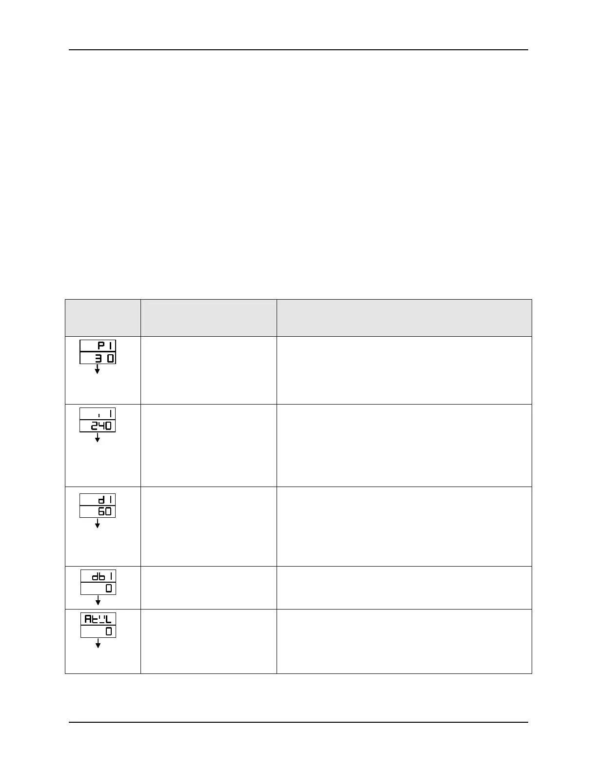
Table 4-1 Configuration 1 Mode
Displays
Default Value
Shown
Parameter Description
.
SETSETSETSET
..
SETSETSETSET
Main Control (OUT 1)
P Value (Proportional Band)
Proportional - Regulates the controller’s output in
proportion to the error signal (the difference between
Process Variable and Setpoint).Range: 0 – 200%
[For On/Off Control, set P1 = 0. The only other
prompt required for setting is HYS 1]
SETSET
Main Control (OUT 1)
I Value (Integral Value)
Integral - Regulates the controller’s output to the size of
the error and the time the error has existed. (The
amount of corrective action depends on the value of
proportional Gain.)
Range: 0 – 3200 seconds
Integral off, I = 0
SETSET
Main Control (OUT 1)
D Value (Derivative Time)
Derivative – Regulates the controller’s output in
proportion to the rate of change of the error. (The
amount of corrective action depends on the value of
proportional Gain.)
Range: 0 – 900 seconds
Derivative off, D = 0
SETSET
Main Control
Dead-Band Time
* DO NOT CHANGE THE VALUE
SETSET
Main Control (OUT 1)
Auto Tuning Offset
For Programmer models-
ATVL means Auto Tuning
Point.
Range: 0 – Upper Limit Value (USPL)
Prevents Overshoot during Autotuning
 Loading...


