Instruction manual - English - EN
5Document 800-23093 Rev. A
6 Installation
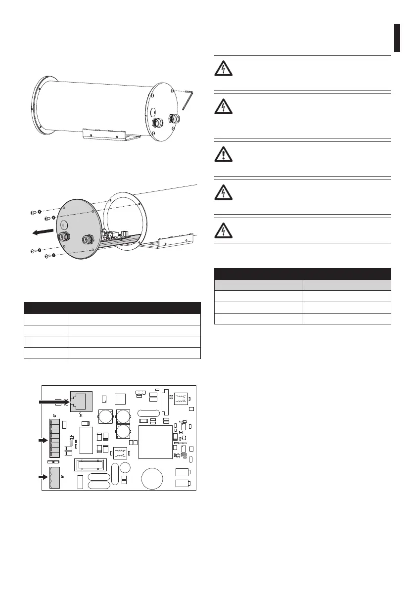
6.1 Opening the camera
Fig. 1
Fig. 2
6.2 Board description
BOARD DESCRIPTION
Connector Function
J1 Power supply for the board
J3 Management I/O
J4 Network interface
Tab. 1
J1
J3
J4
Fig. 3
6.3 Connection of the power
supply line
Electrical connections must be performed
with the power supply disconnected and
the circuit-breaker open.
When commencing installation make sure
that the specications for the power supply
for the installation correspond with those
required by the device.
Earth cable should be about 10mm longer
than the other two, so that it will not be
disconnected accidentally if pulled.
Make sure that the power source and
connecting cables are suitable for the
power consumption of the system.
The connection must not be accessible to
the operator.
Connect the power supply cables to the J1 terminal
as described in the table.
CONNECTION OF THE POWER SUPPLY LINE
Colour Terminals
Dened by the installer N (Neutral)
Dened by the installer L (Phase)
Yellow/Green GND
Tab. 2
6.4 Connection of the Ethernet
cable
Connect the J4 connector of the secondary connector
board using a 5E category, or higher, UTP cable.
 Loading...