EN - English - Instruction manual
6 Document 800-23093 Rev. A
6.5 Relay connection
The relay can be used for low working
voltages only (up to 30Vac or 60Vdc) and
with a maximum current of 1A. Use cables
with a section suitable for the load to be
controlled. Use cables with a minimum
section of 0.25mm² (AWG 24) and maximum
section of 1.5mm² (AWG 16).
The connection must not be accessible to
the operator.
The RL relay clamps are located in the J3 connector.
The relay has no polarity and therefore the terminals
can be used indierently, with alternating or
continuous current.
RELAY CONNECTION
Terminal Description
RL Relay terminals
Tab. 3
6.6 Factory reset
The external relay and alarm cable shield
must be earthed.
To restore the factory default settings connect the
contacts as shown in gure (AL1, GND).
AL1 GND
Fig. 4
6.7 Washing system connection
(optional)
The wash system terminals are situated in connector
J3. Control takes place using a serial line RS485.
CONNECTING THE WASHER
Serial line Terminal Description
RS-485 A (+) RS-485 line
B (-) RS-485 line
Tab. 4
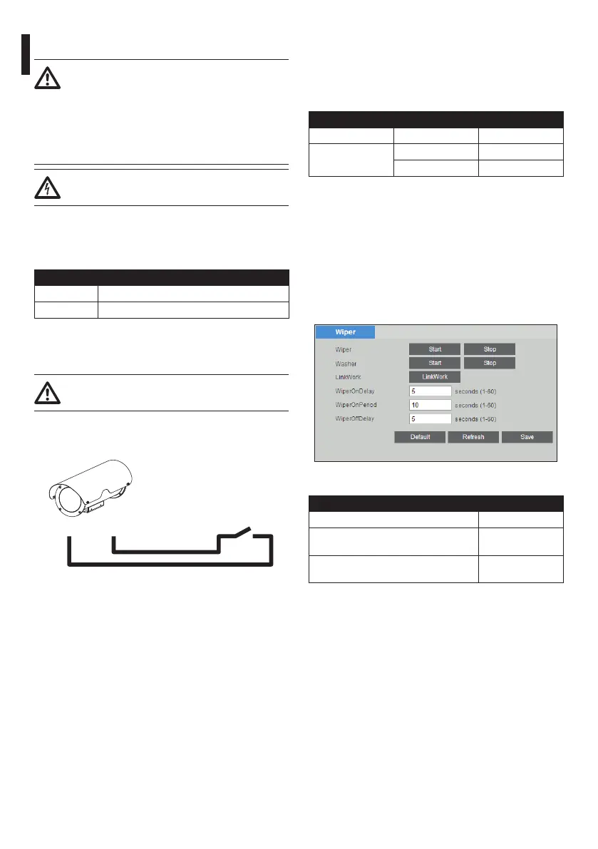
6.8 Wiper and Washer controls
6.8.1 Special controls
The camera’s web UI supports Wiper and Washer
setting and control.
Settings can be congured in: CAMERA>>LOGIN>>SE
TUP>>SYSTEM SETUP>>PERIPHERAL
Fig. 5
SPECIAL CONTROLS
Action Preset
Run wiper once when system calls the
preset.
103
Run washer once when system calls the
preset
112
Tab. 5
 Loading...