WIRING
TrueSTEAMwiringisdifferentfromevaporativepadhumidierwiring.Inadditiontosolenoidwatervalve
actuation,TrueSTEAMcanmonitorsystempowerandregulatesystemfanoperation.
Using the DIP Switches
ThewiringfeaturesareconguredbyDIPsettings,whicharedescribedundertheTrueSTEAMcover.
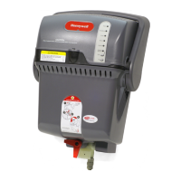
STEP ONE: Remove the TrueSTEAM Cover
Loosenthecoverscrew.
Slidecoveroutfromfront.
Withthecoverremoved,youwillseesixDIPswitches
totheleftoftheuserinterfacepanel.Thismanual
referstoDIPs1–6fromlefttoright.
STEP TWO: Understand the DIP Switches
DIPS 1 and 2 are used for maintenance.
DIP 1 and DIP 2:Together,thesetwoDIPsspecify
howoftentheautomaticushcycleisperformed.See
“Set the Automatic Flush Cycle Timing” on page 13.
Before Wiring TrueSTEAM
BeforewiringtheTrueSTEAM:
Iwillreadthesection“UsingtheDIPSwitches”beginningonthispage
Iwillreadthesection“DecidingontheWiringConguration”beginningonpage14
CAUTION: Voltage Hazard.
Be sure TrueSTEAM is not plugged in when removing the cover.
TrueSTEAMHumidicationSystem69-2285EF—01
12
1
2
3

 Loading...