WIRING
YouwillneedtowireTrueSTEAMusingthediagramthatappliestoyourhumiditycontrol.Rememberto
includethewiringandDIPsettingsrequiredforpowermonitoring,systemfanregulation,andadd-onair
proving(ifused).
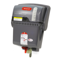
Using the Terminals
Wiring the TrueSTEAM
Use the terminals (found inside the cover) to
wireTrueSTEAMtothehumiditycontrolandthe
HVACsystem.
RedLINK Wireless Terminals
A–Hot
B–Sendsignal
C–Receivesignal
D–Common
Note:Ifusingwirelesscontrol,setDIPs3and4totheUPposition.
Low-voltage Terminals
24V–Outputvoltage
HUM–Low-voltageterminalsforhumiditycontrol.
C,R–InputsfromHVACsystemtransformer.
GT,GF–GTinputisfromthermostatG.GFoutput
goestoHVACsystemG.
Routewiresthroughtheraisedtabsandoutthenotch
attherearofthechassis.
Makesurethewiresaresecureanddonotinterfere
withthecoverassembly.
Routing the Wires
24V
24V
HUM
HUM
C
GT
R
RT
GF
EXT
A
B
C
D
M29620
TrueSTEAMHumidicationSystem69-2285EF—01
19
1
2

 Loading...