Impact / Impact Pro / Impact Pro IR Operating Instructions
79
Additional marking instructions, according to EU Directive 94/9/EG in •
particular, are unaffected. The manufacturer confirms with this type
label that the instrument supplied contains the documented features and
technical characteristics as described in this report. Each instrument
without such a label does not conform to this report.
A complete copy of this report and the test reports PFG-No. 41300502 and •
PFG No. 41300502P NI to 41300502P NIV will be made available upon
the request of the user.
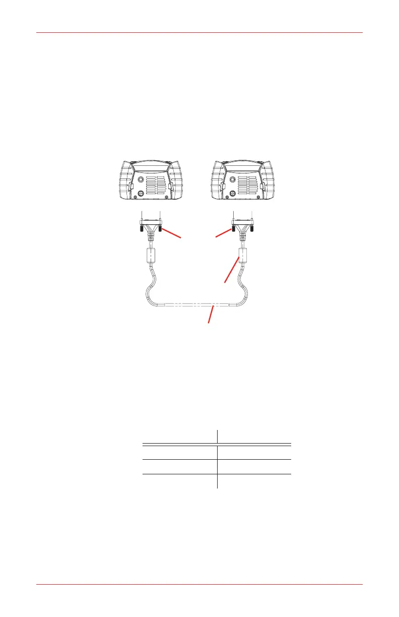
B�2�4 Safelink Connection Drawing
Impact Portable Unit 1 Impact Portable Unit 2
Screw
(4 places)
Ferrite
Torroidal Core
Cable
Overall Foil/Braid Shield
Length between plugs = 100 Meters max (328 ft max)
Note
Only two units may be permitted to be connected.1.
Safelink cable assembly is connected to ‘Data Connector’ on 2.
base of impact portable and retained via 2 position screws into
baseplate.
Cable is 2 connector with overall foil/braid shield.3.
Data Connector Data Connector
PIN 12 (CAN H) PIN 12 (CAN H)
PIN 13 (CAN L) PIN 13 (CAN L)
PIN 14 (DGND) PIN 14 (DGND)
PIN 14 Connects to braid/screen
Alternatively, interconnection may be made between impact units 4.
located in hazardous and non hazardous areas.
 Loading...