Installing the MPA2 Panels
Installation
MPA2 Access Control Unit Installation Guide, Document 800-25395 - B 25
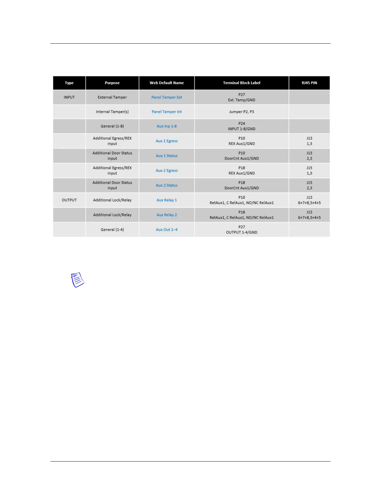
Table 6 Factory Default Configuration Additional Inputs/Outputs
Notes:
• The Controller Board includes Inputs 6 and 8 but they are reserved
for system use.
• Reader LED, while it is an output, should never be used to control
anything other than its associated reader’s LED.
• MPA2 supports a variety of Wiegand reader models. Some readers
have only one brown wire for LED control; others have two possible
LED control inputs--orange for the green LED and brown for the red
LED. RED is the normal state of the Reader LED operation. The LED
turns GREEN for two seconds after a valid card read. Although
readers operate similarly, LED control can vary, depending on the
manufacturer. Therefore, your readers may require some testing to
identify the right LED wire when the reader uses Dual LED wires. If
you are using Dual Line LED control, it’s recommended that you try
the ORANGE-colored wire for a GREEN LED.
• The Reader Buzzer feature is shared with the RED LED signal on the
MPA2 panels.
• In case 2 Readers are used per door (Exit + Entry) with WIEGAND,
then the used Readers should support Hold A/B lines.