28 www.honeywell.com
Installing the MPA2 Panels
Installation
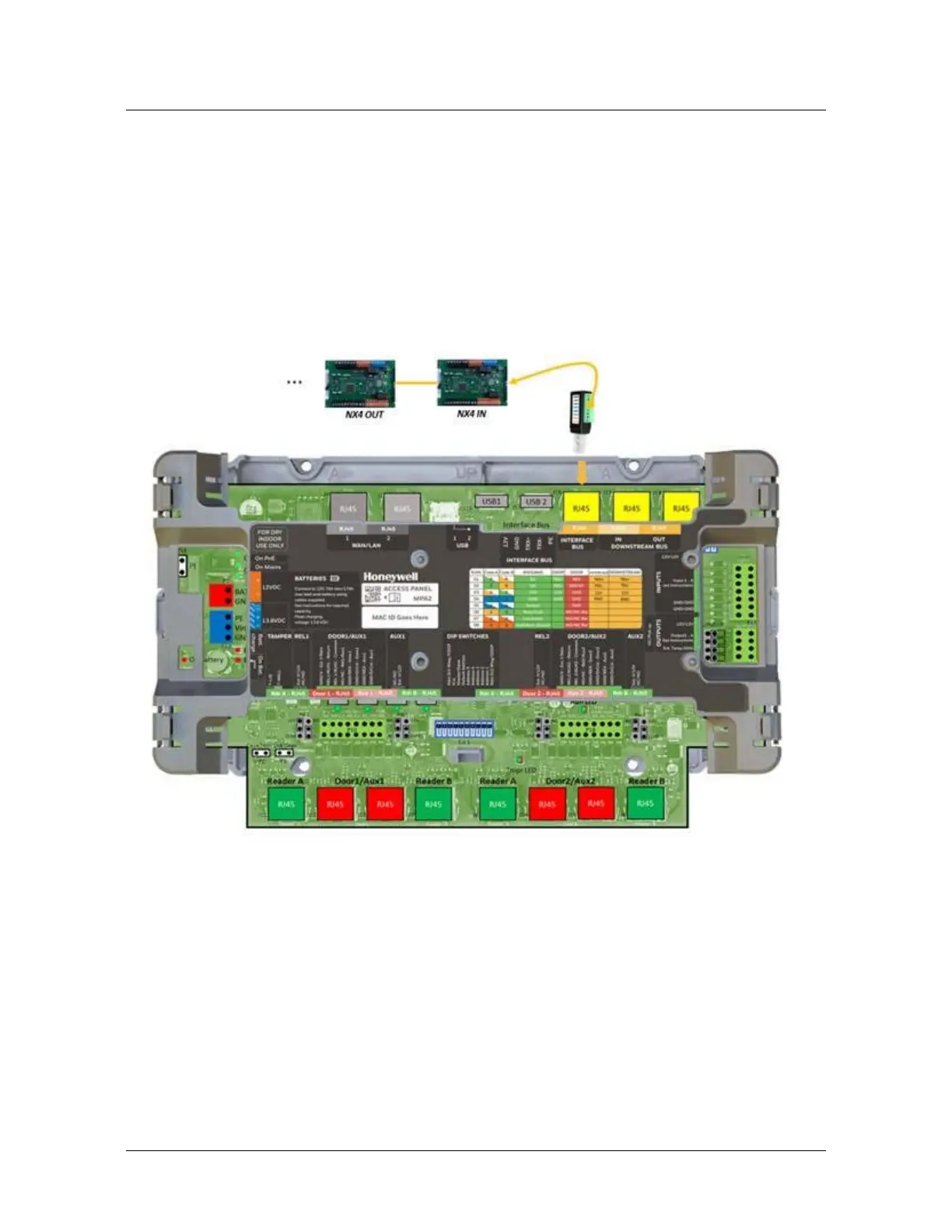
3.4 Wiring the RS485 bus connections
3.4.1 RS485 Interface bus (IB2 = future development / NX4-I/O =
USA only) J16
The MPA2 panel has a dedicated RS-485 Interface bus for connecting
extra I/O. A maximum of two NX4IN and a maximum of four NX4OUT for a
total of six Downstream I/O Devices can be added to the downstream bus.
The Interface bus is wired into the MPA2 using standard RJ45 connection
(Preferably use CAT 7 S/FTP cable) (J16) on the board. Use pin1&2
(TRX+/TRX-) to connect the NX4 I/O boards. Make sure the NX4 I/O boards
are powered with an external 24Vdc Power supply. If the MPA2 controller is
physically terminating one end of the RS-485 bus line as shown below, S1
positions 5 & 6 need to be set to ON