Installing the MPA2 Panels
Installation
MPA2 Access Control Unit Installation Guide, Document 800-25395 - B 39
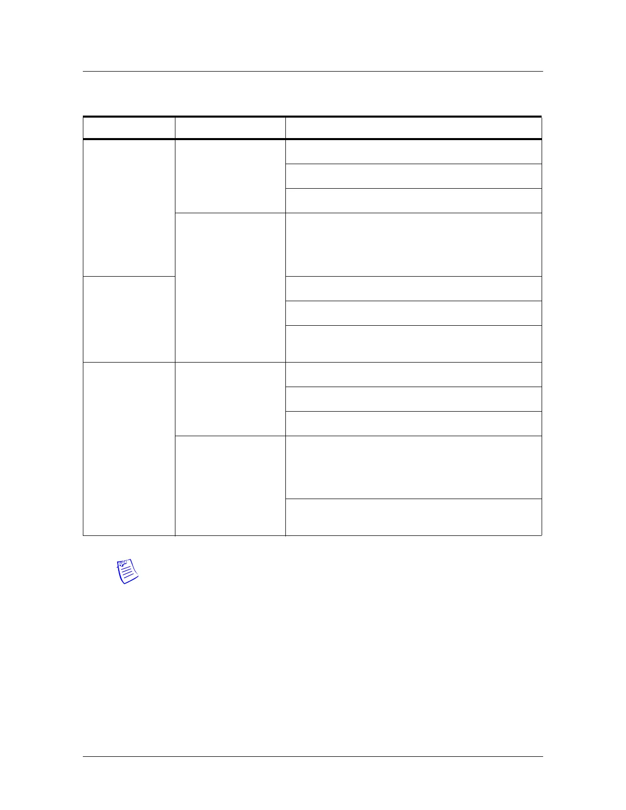
Table 9 Downstream I/O Devices DIP Switch and Jumper Settings
Note: If a NX4IN is not required in a system, start addressing the NX4OUT at
DIP switch 3. If a NX4IN is configured with an address other than 1 or 2, the
MPA2 panel will not communicate with it. Likewise, if a NX4OUT is
configured with an address other than 3 through 6, the MPA2 panel will not
communicate with it.
The MPA2 board is not intended to provide either module power or module
output load power for downstream I/O. A separate 24 VDC supply should
be used to provide power to all downstream modules and output loads.
Module Setting Value
NX4IN DIP switches Address (switches 1-6) - 1 or 2
Baud rate (switches 7 and 8) - 7 = OFF, 8 = ON
OP Mode (switches 9 and 10) - 9 = OFF, 10 = OFF
Jumper settings JP1 – ON, positions 1 and 2 (if the module is the
last module on the downstream bus),
OFF positions 2 and 3 (if the module is not the last
module on the downstream bus)
JP2 - any setting
JP3 - any setting
JP4 - NORMAL
(Positions 1 and 2)
NX4OUT DIP switches Address (switches 1-6) - 3 through 6
Baud rate (switches 7 and 8) - 7 = OFF, 8 = ON
OP Mode (switches 9 and 10) - 9 = OFF, 10 = OFF
Jumper settings JP1 - ON, positions 1and 2 (if the module is the last
module on the downstream bus);
OFF, positions 2 and 3 (if the module is not the last
module on the downstream bus)
JP2 - NORMAL, positions 1
and 2