30 www.honeywell.com
Installing the MPA2 Panels
Installation
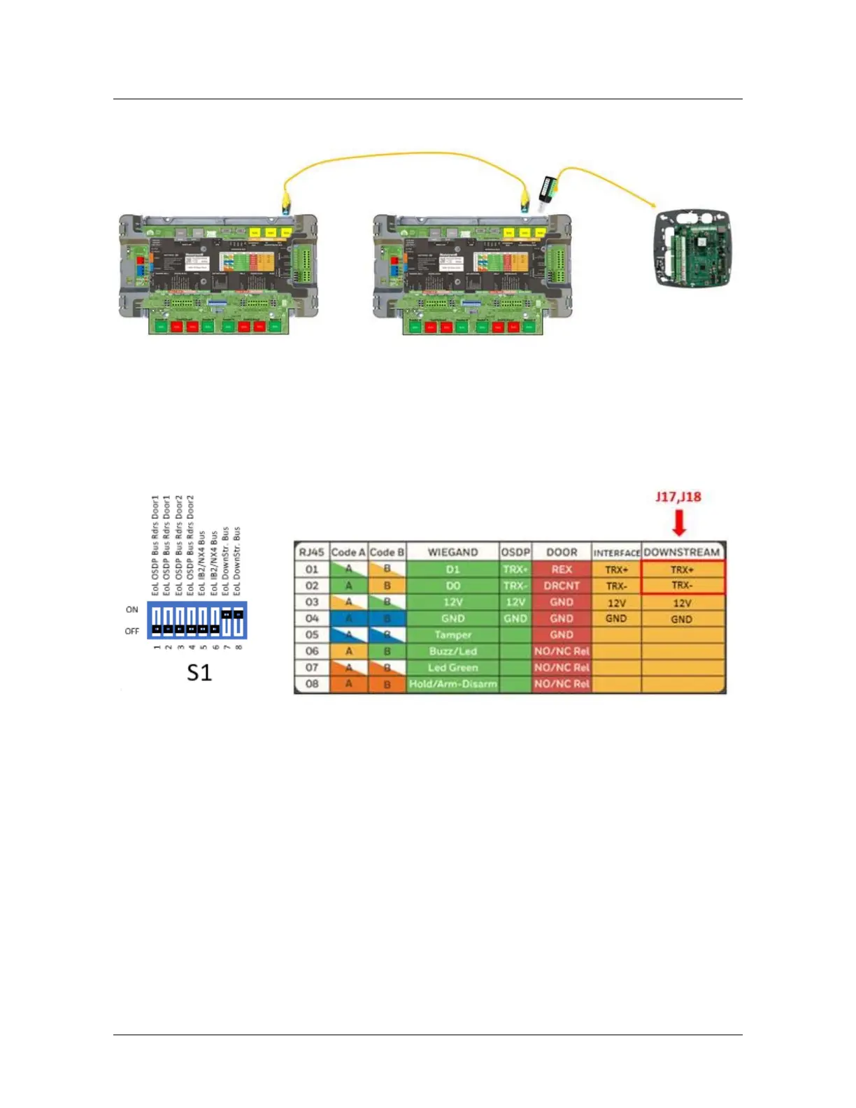
The Downstream bus is wired from/into the MPA2 using standard RJ45
connections on the board (J17 IN/J18 OUT) (Preferably use CAT 7 S/FTP
cable). Use pin1&2 (TRX+/TRX-) to connect the downstream panels. Make
sure the downstream panels are powered by their local Power supply. If the
MPA2 controller is physically terminating one end of the RS-485 bus Line,
S1 positions 7 & 8 need to be set to ON.