52 TR50 - User Guide
Step 7. Drag-drop any logic slot or Math slot from the Palette into the wire sheet
and click OK.
Step 8. Link the Controller Alarm to the added slot.
By the above process, user can write back the alarm value into the TR50 from the
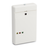
controller. Based on the values the LED will blink red, yellow, and green.
4.6.1.3 Sensor Failure
The sensor failure monitors the current state of the sensors. If there are any
physical failure of the sensors, the different states will be reported using the
sensor failure.
Add a sensor failure and link the respective parameter which user want to monitor
for the sensor failure.

 Loading...


