MAN1032-10-EN_EXL6_UserManual
March 12, 2020 73 | 191
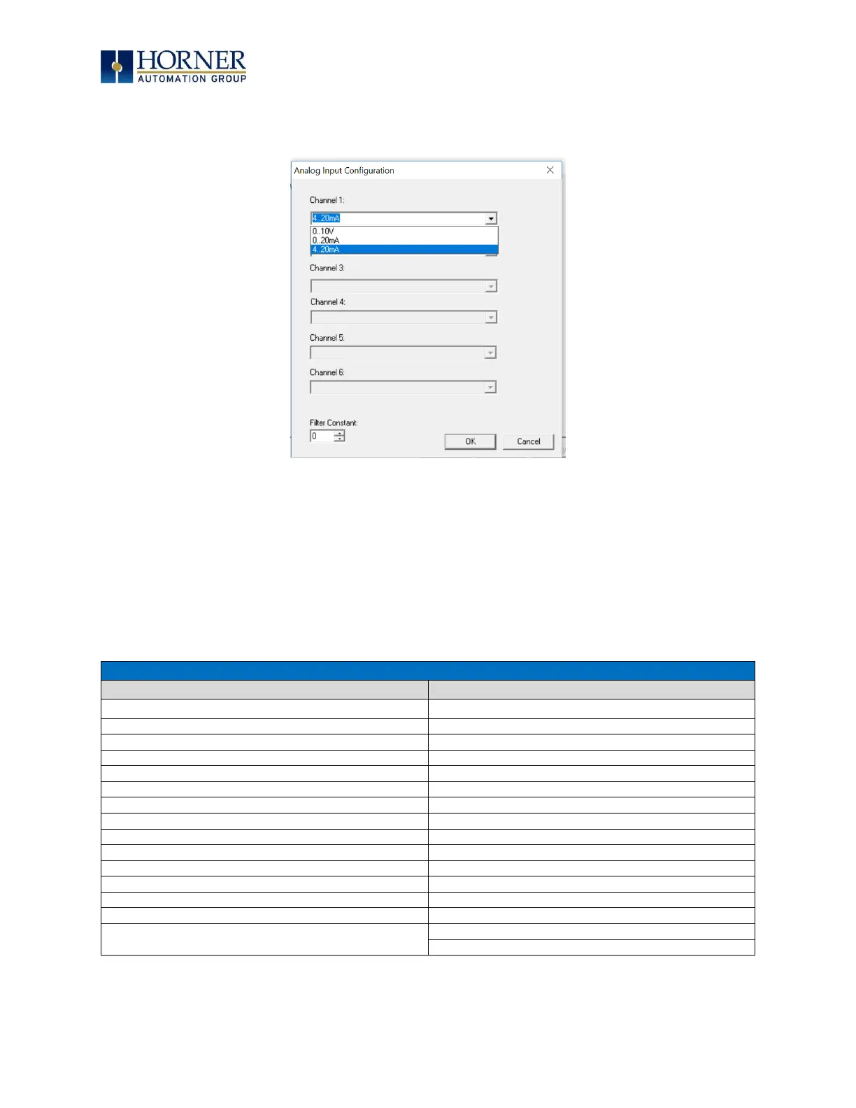
7.7 Analog Input Configuration
The following figure illustrates the Analog Input Configuration dialog.
Figure 7.9 – Analog Input Configuration Dialog
The Channel x drop down windows allow the user to specify the mode for each analog input to
operate. The Channel x drop down windows are enabled/disabled according to which model is
being configured. All of the models have the following modes available:
- 0..10V
- 0..20mA
- 4..20mA
On Model 5 and Model 6 I/O, other options on channels are outlined below:
Table 7.2 – Analog In for Models 5 & 6
Type J Thermocouple, 1/20°C
Type K Thermocouple, 1/20°C
Type N Thermocouple, 1/20°C
Type J Thermocouple, 1/20°C
Type T Thermocouple, 1/20°C
Type K Thermocouple, 1/20°C
Type E Thermocouple, 1/20°C
Type N Thermocouple, 1/20°C
Type R Thermocouple, 1/20°C
Type T Thermocouple, 1/20°C
Type S Thermocouple, 1/20°C
Type E Thermocouple, 1/20°C
Type B Thermocouple, 1/20°C
Type R Thermocouple, 1/20°C
* The Filter Constant provides filtering to all channels.
Type S Thermocouple, 1/20°C
Type B Thermocouple, 1/20°C