MAN1032-10-EN_EXL6_UserManual
March 12, 2020 76 | 191
Figure 8.1 – Removing the I/O Cover
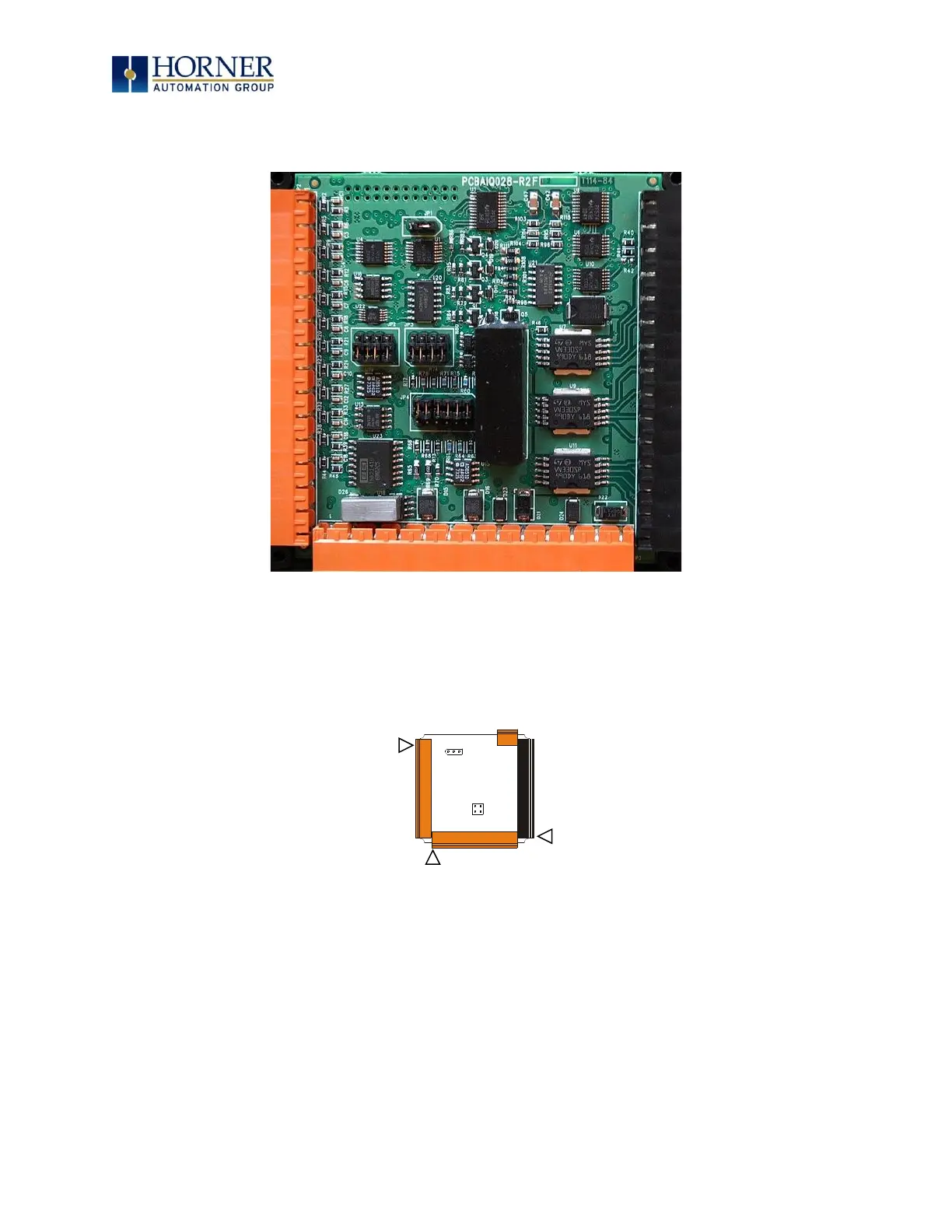
Figure 8.2 – EXL6 I/O Cover Removed (sample I/O board)
Once the back is removed the jumper selection can be changed. The jumper settings are
documented on each data sheet using a diagram such as Figure 8.3 below and a description of
the jumper settings.
Figure 8.3 – Example Jumper Diagram
To re-install the cover, place the I/O cover back on the unit.
Place the screw back into the hole and turn the screw slowly counterclockwise until it clicks into
the threads. This prevents the screw from being cross-threaded. Now turn the screw clockwise
until the cover is firmly secured. Repeat this process for all four (4) screws.
Ensure not to exceed the recommended max torque of 7-10 in-lbs [0.8 – 1.13 N-m.]