MAN0964-13-EN_XL4_UM
A u g u s t 6 , 2 0 2 1 P a g e 79 | 194
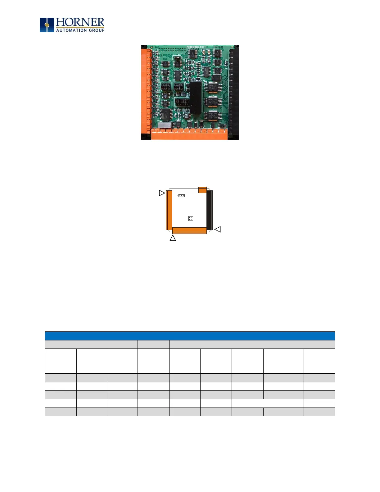
Figure 8.2 – XL4 I/O Cover Removed (sample I/O board)
Once the back is removed, the jumper selection can be changed. The jumper settings are
documented on each data sheet using a diagram such as Figure 8.3 below and a description of
the jumper settings.
Figure 8.3 – Example Jumper Diagram
To re-install the cover, place the I/O cover back on the unit. Place the screw back into the hole
and turn the screw slowly counter clockwise until it clicks into the threads. This prevents the
screw from being cross-threaded. Now turn the screw clockwise until the cover is firmly
secured. Repeat this process for all four (4) screws. Ensure not to exceed the recommended
max torque of 7-10 in-lbs [0.8 – 1.13 N-m].
8.3 Model and I/O Overview
Table 8.1 shows the different types of I/O included with the various XL4 OCS models. Specific
specifications, jumper settings, and wiring diagrams can be found on the XL4 Datasheets.