MAN0964-13-EN_XL4_UM
A u g u s t 6 , 2 0 2 1 P a g e 80 | 194
8.4 Solid-State Digital Outputs
Solid-state digital outputs are generally used to activate lamps, low voltage solenoids, relays,
and other low voltage and low current devices.
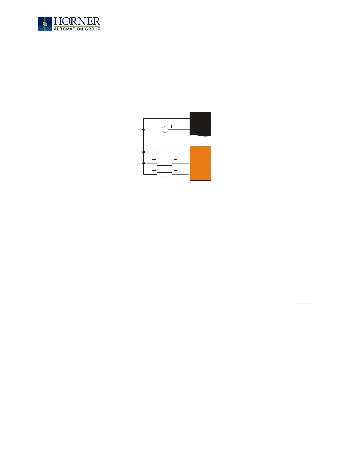
NOTE: The digital outputs used on the XL4 OCS are “sourcing” outputs. This means the output
applies a positive voltage to the output pin when turned ON. When turned off, the output applies
approximately zero volts with respect to the I/O ground.
Figure 8.4 – Typical Output Wiring
The digital outputs used in the XL4 OCS have electronic short circuit protection and current
limiting. While these electronic protections work in most applications, some application may
require external fusing on these outputs.
The digital outputs in the XL4 OCS are typically controlled via %Q bits in the register
mapping. Some of the outputs are designed for high-speed applications and can be used for
PWM or frequency output applications. Please see the data sheet and the chapter on High
Speed I/O for additional information.
When the controller is stopped, the operation of each output is configurable. The outputs can
hold the state they were in before the controller stopped or they can go to a predetermined
state. By default, digital outputs turn off. For more information on Stop State, see the Index to
find pages referencing Cscape settings.
The digital outputs feature an output fault bit, %I32, will turn on if any of the outputs
experience a short circuit, over-current, or the output driver overheats.