10
Installing Pull Arm
Tension the closing spring (Fig.17) to EN4
Remove guide cover (A)
Drill 4 holes along “V” mark on guide profile (B)
Position guide profile (B) horizontal to door leaf according to
dimensions in Fig.5
Secure guide to door leaf using suitable fixings
Insert slide coupling (C) within the guide (B)
Close door
Locate spindle (G) on output shaft so that end of arm (F) meets the
slide coupling (C).
Detach arm (F) from spindle (G)
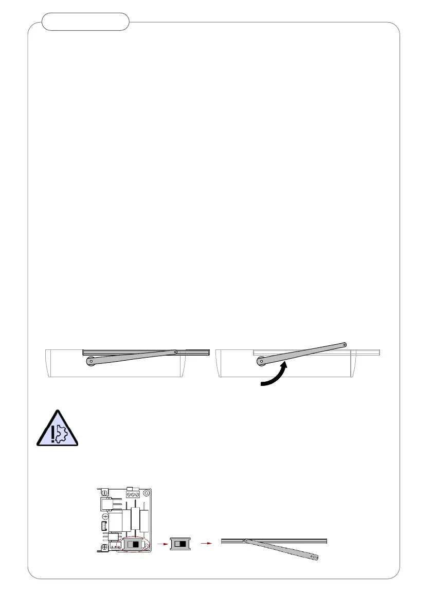
Remove spindle (G) from output shaft and rotate 1 to 3 teeth (5 to
15°) in the direction of door to tension spring (Fig. 8) and replace.
Insert washer (H) and secure screw (I) into spindle
Locate and secure arm (D) to spindle (G).
Rotate arm to reach the coupling (C)
Secure coupling (C) to arm (F)
Insert guide cover profile (A) and end caps (E,D)
Fig.8 Pull arm pre-tensioning
Misalignment of operator in relation to door leaf movement will
effect a bending force upon the arm causing the slide coupling to
bind and damage the operator.
Arm Type Selection
Set slide switch to pull arm position.
Fig.9 Arm type selector switch