11
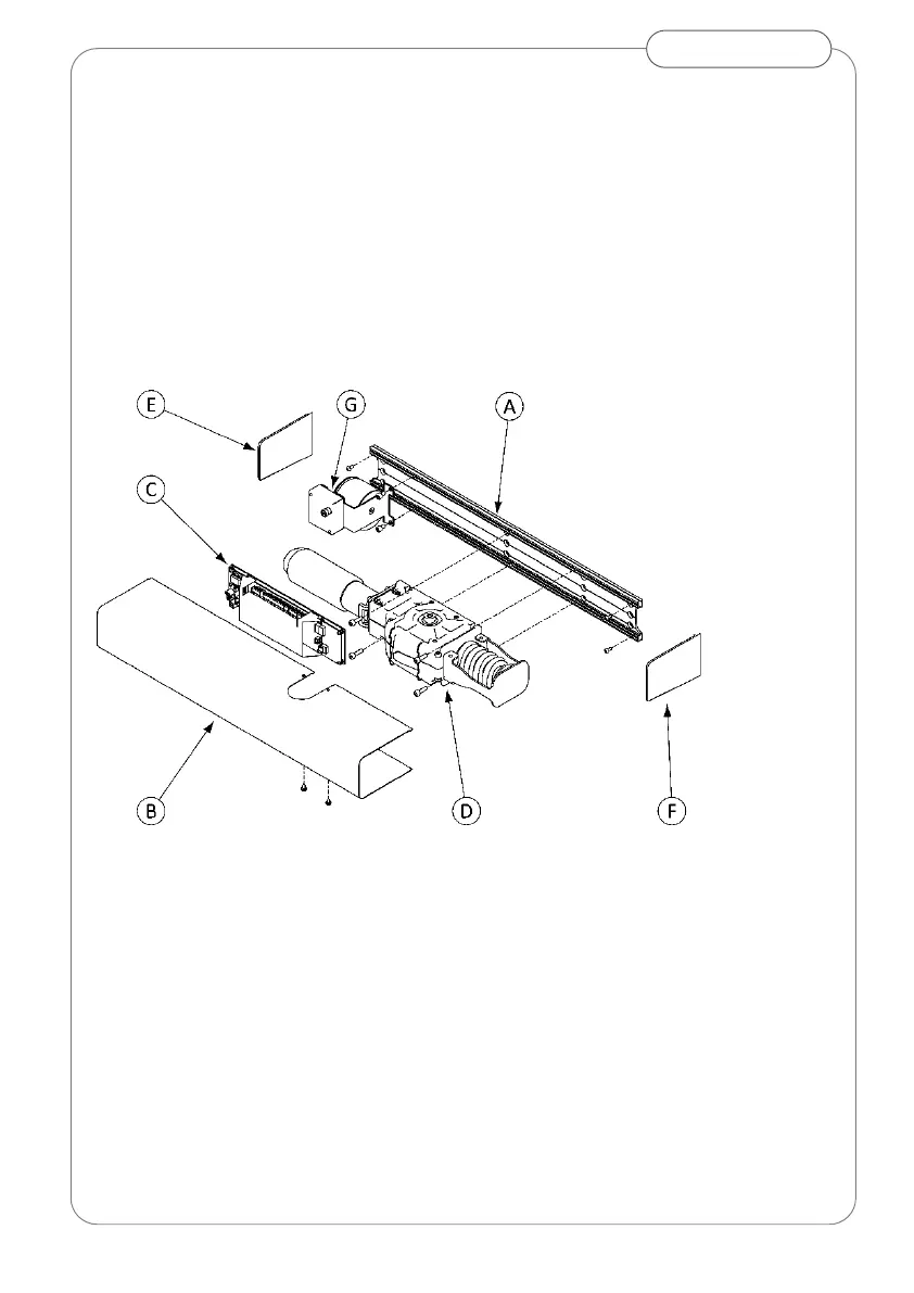
Push Arm
Preparation
Proceed as follows:
remove cover (B);
disconnect wiring from control board (C);
release the 2 captive screws and remove control board (C)
remove the 2 screws and remove transformer (G);
remove the 4 screws and remove gear motor (D);
loosen the 4 screws and remove end caps (E) and (F);
Fig.10 Exploded view
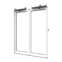
Mounting Operator
Position and secure the base plate in relation to pivot axis and door leaf, as
shown in Fig.11 dependent on door hand
Base plate outer edge should align with the pivot axis.
Base plate lower edge must parallel to door leaf top edge
Vertical dimension “L” between bottom of base plate and
centreline of cleat fixing is spindle length (fig 3) +5mm.