56
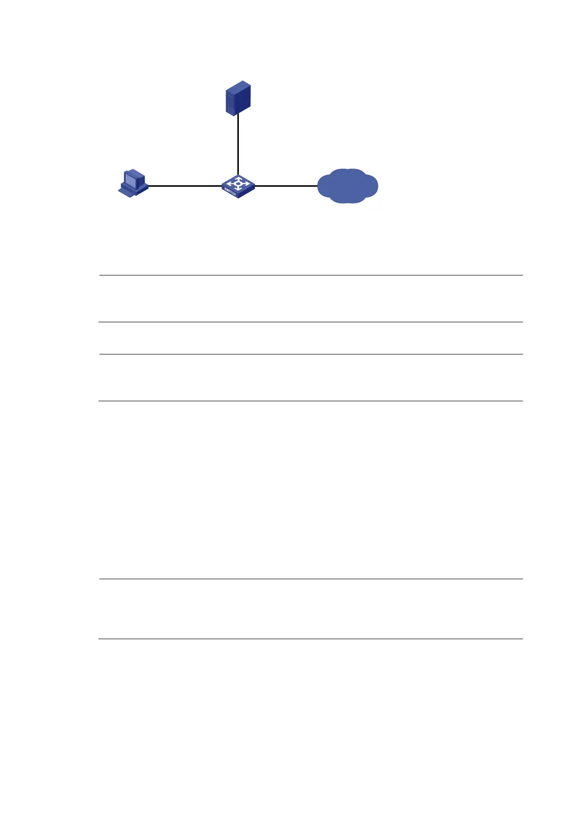
Figure 16 Network diagram
Internet
Portal user
192.168.1.58/24
Gateway : 192.168.1.70/24
RADIUS server / Portal server
10.1.1.1/24
Vlan-int2
192.168.1.70/24
Vlan-int3
10.1.1.2/24
Switch
Configuration procedure
NOTE:
Configure IP addresses for the devices as shown in Figure 16 and mak
e sure that devices can reach each
other.
1. Configure the RADIUS server (iMC PLAT 5.0)
NOTE:
This example assumes that the RADIUS/Portal server runs iMC PLAT 5.0 (E0101), iMC UAM 5.0 (E0101),
and iMC CAMS 5.0 (E0101).
# Add an access device.
Log in to the iMC management platform, click the Service tab, and select User Access Manager > Access
Device from the navigation tree to enter the Access Device page. Then, click Add to enter the Add Access
Device page and perform the following configurations:
• Set the shared key for secure authentication and accounting communication to expert
• Specify the ports for authentication and accounting as 1812 and 1813 respectively
• Select LAN Access Service as the service type
• Select HP(A-Series) as the access device type
• Select the switch from the device list or manually add the switch whose IP address is 10.1.1.2
• Adopt the default settings for other parameters and click OK.
NOTE:
The IP address of the access device specified here must be the same as the source IP address of the RADIUS
packets sent from the switch, which is the IP address of the outbound interface by default, or otherwise the
IP address specified with the nas-ip or radius nas-ip command on the switch.

 Loading...


