3-12
Performance Tests
PDH Transmitter Output (UKK, [USB], UKJ, [USA]
9. Select TERMINATION [120Ω BAL] on the display.
10. Repeat steps 4 through 7.
2.048 Mb/s Unbalanced Output
11. Select SIGNAL [2 Mb/s]; TERMINATION [75Ω UNBAL].
12. Connect the Unbalanced 75Ω SIGNAL OUT port to the Oscilloscope Input 1.
Set the oscilloscope termination to 1ΜΩ and press on the
oscilloscope.
13. Adjust the Oscilloscope Timebase and Delay to position the positive peak pulse
amplitude at mid-pulse-width point in the centre of the screen.
14. Measure the peak pulse amplitude at mid-pulse-width using the Oscilloscope and
verify that this is between 2.133V and 2.607V.
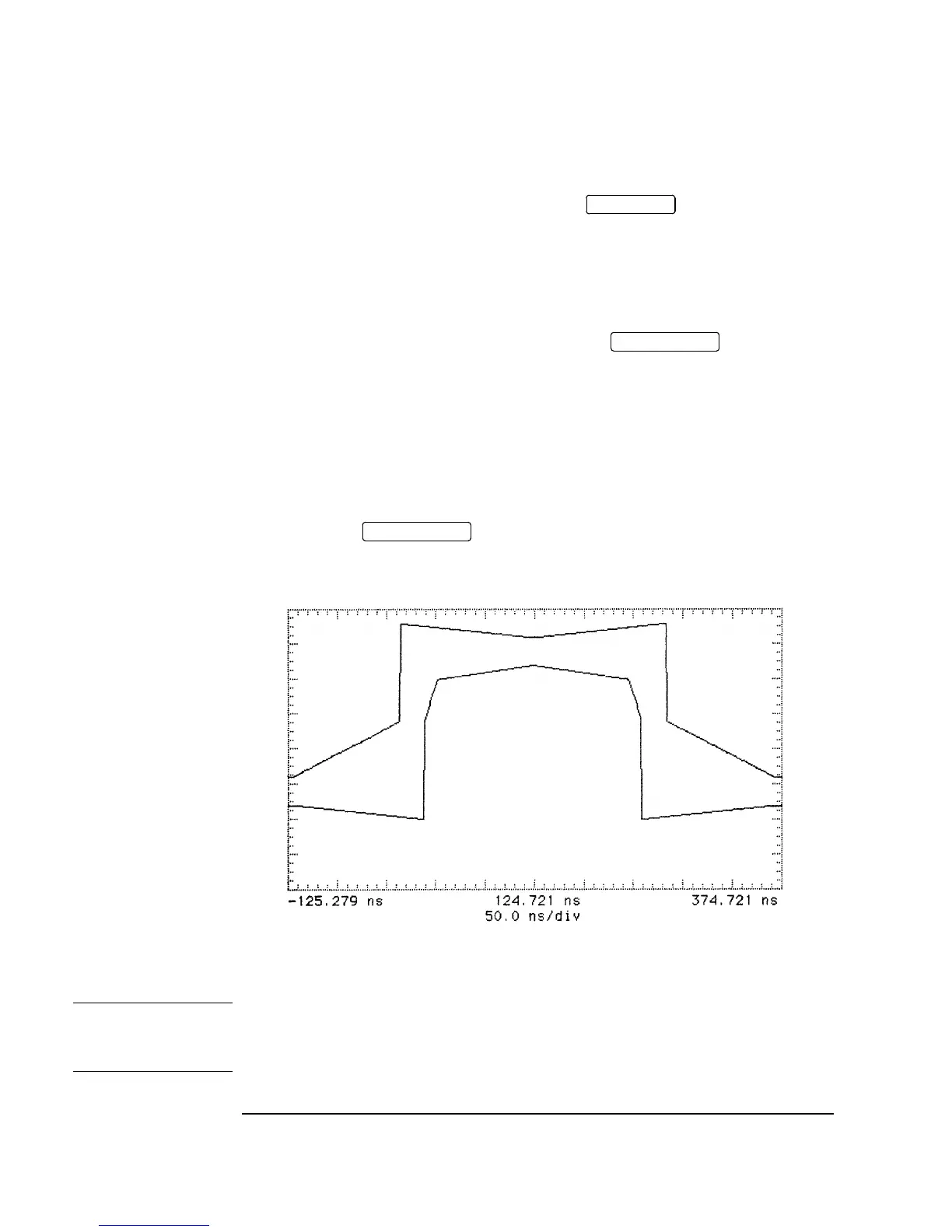
15. Select the 2Mb G.703 mask on the oscilloscope and store it on the display.
16. Press SHIFT on the oscilloscope to automatically align the pulse
to the mask in Figure 3-2. Verify that the pulse falls within the mask as shown in
Figure 3-3.
Figure 3-2 2 Mb/s Pulse Mask
NOTE If your oscilloscope does not have the Mask feature, obtain a printout of the displayed
pulse. Place the mask, shown in Figure 3-2, over the pulse and ensure that the pulse
falls within the mask. (A transparent copy of the mask should be used).
TRANSMIT
AUTOSCALE
AUTOSCALE

 Loading...


