3-121
Performance Tests
STM-1/STM-4 Optical Interface (Options 130, 131)
NOTE If the input power is greater than -8 dBm then the Optical/Electrical converter is liable
to saturate.
33. Disconnect the output of the O/E Converter from the oscilloscope and connect
instead to the HP 37717C STM1/4 Optical Module Monitor Input.
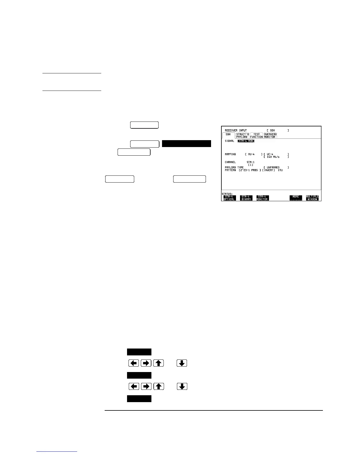
34. Press on the HP 37717C
and set up the display as shown opposite.
35. Press
then to start the measurement.
36. After 5 minutes, check that NO
TROUBLE is displayed on the HP 37717C
display. Press to
stop the measurement.
37. Recall the HP 37717C DEFAULT SETTINGS as shown on 3-2.
38. Verify that the Optical Module LASER ON led is NOT lit indicating that the laser
is disabled before continuing.
39. Repeat steps 26 through 38, selecting SIGNAL [STM-1 OPT] [1310 nm] in step
30 and [STM-1 MON] in step 34.
40. Repeat steps 26 through 38, selecting SIGNAL [STM-0 OPT] [1310 nm] in step
30 and [STM-1 MON] in step 34.
Procedure Option 130 only
41. Set the Optical Attenuator to WAVELENGTH 1550 nm ; CAL=0.
Connect the HP 37717C 1550 nm Optical Out Port to the HP 8153A Power Meter via
the HP 8157A Optical Attenuator, set to ATTEN 10 dB - ensure that all connections
are tight and that optical cables have no twists or tight bends.
42. Setup the HP 8153A as follows:
a. Press key to display wavelength [λ]
b. Using , and keys, set the wavelength to 1550nm.
c. Press key to display Time [t]
d. Using , and keys, set the time to 200mS.
e. Press key to display REF.
RECEIVE
RESULTS
TROUBLE SCAN
RUN/STOP
RESULTS
RUN/STOP
PARAM
PARAM
PARAM

 Loading...


