3-28
Performance Tests
Multiple PDH Transmitter Outputs (Options UHC, [US6])
NOTE If your oscilloscope does not have the Mask feature, obtain a printout of the displayed
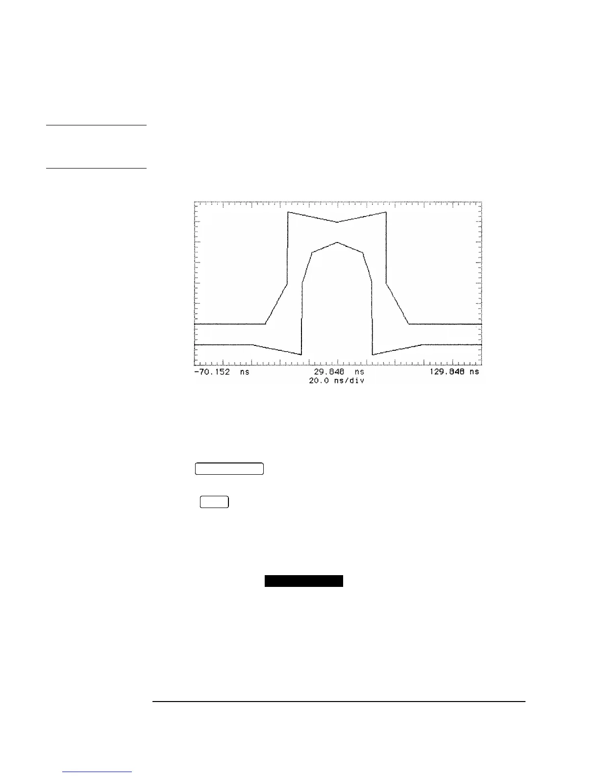
pulse. Place the mask shown in Figure 3-17 over the pulse and ensure that the pulse
falls within the mask (a transparent copy of the mask should be used).
Figure 3-17 8 Mb/s Pulse Mask
46. Repeat steps 42 to 45 with the Oscilloscope Channel 1 connected to SIGNAL
OUT 3 and SIGNAL OUT 4 in turn.
47. Press on the oscilloscope to display the full waveform and use the
following sequence to display the isolated negative pulse:
Select menu.
Set trigger level to middle of negative pulse.
Set Trigger to PATTERN.
Set Sequence toHXX.
48. Use the oscilloscope function to display an inverted pulse
mask on the oscilloscope.
49. Adjust the oscilloscope timebase, delay and vertical sensitivity controls to verify
that the pulse meets the mask as shown in Figure 3-17. Use the displayed settings as
a guide.
50. Measure the peak pulse amplitude at mid-pulse-width using the Oscilloscope and
verify that this is between 2.133V and 2.607V.
AUTOSCALE
TRIG
STORE INVERT

 Loading...


