3-30
Performance Tests
Multiple PDH Transmitter Outputs (Options UHC, [US6])
66. Select the 34Mb/s G703 Mask on the oscilloscope and store it on the Display.
67. Press SHIFT on the oscilloscope to automatically align the pulse
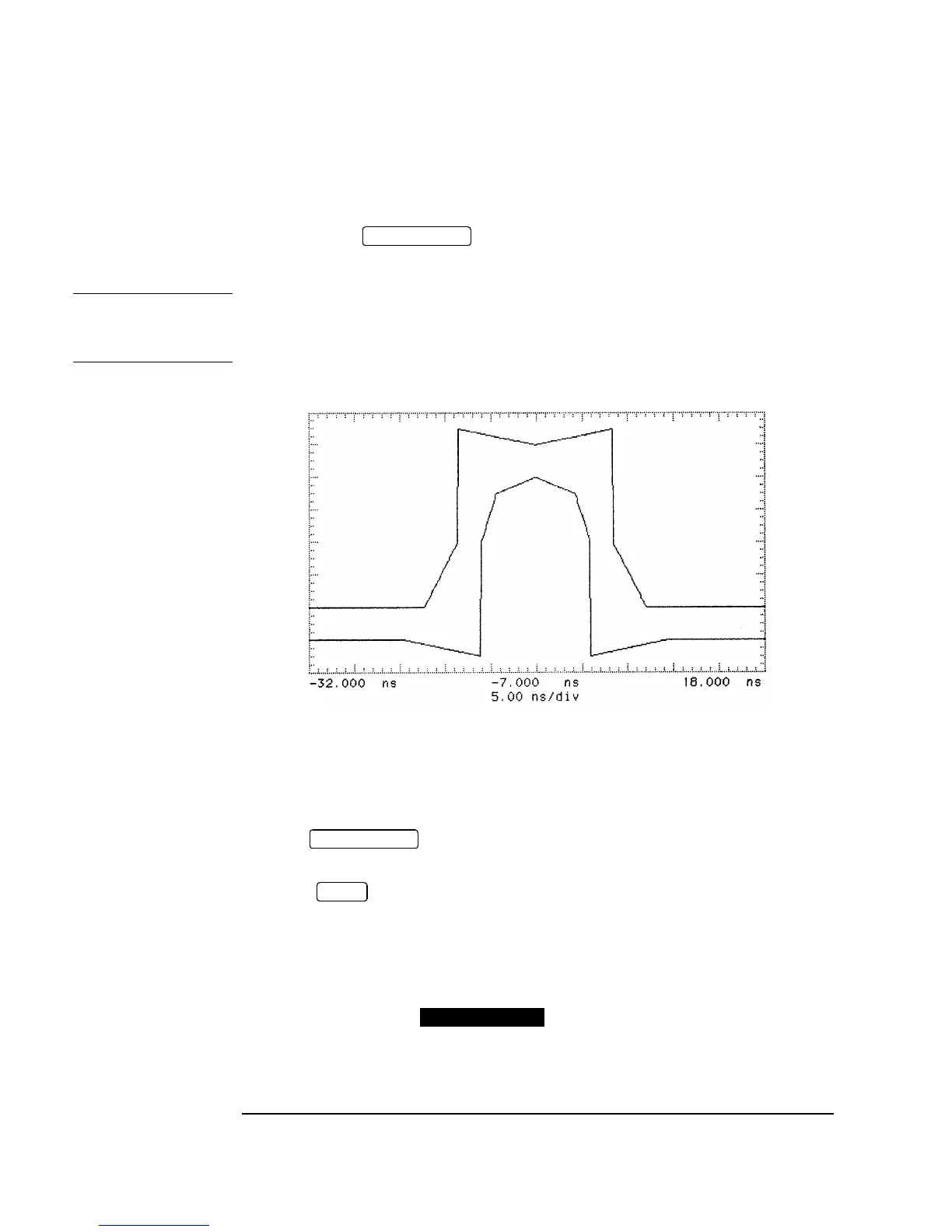
to the mask. Verify that the pulse falls within the mask as shown in Figure 3-18.
NOTE If your oscilloscope does not have the Mask feature, obtain a printout of the displayed
pulse. Place the mask shown in Figure 3-18 over the pulse and ensure that the pulse
falls within the mask (a transparent copy of the mask should be used).
Figure 3-18 34 Mb/s Pulse Mask
68. Repeat steps 64 to 67 with the Oscilloscope Channel 1 connected to SIGNAL
OUT 3 and SIGNAL OUT 4 in turn.
69. Press on the oscilloscope to display the full waveform and use the
following sequence to display the isolated negative pulse:
Select menu.
Set trigger level to middle of negative pulse.
Set Trigger to PATTERN.
Set Sequence toHXX.
70. Use the oscilloscope function to display an inverted pulse
mask on the oscilloscope.
AUTOSCALE
AUTOSCALE
TRIG
STORE INVERT

 Loading...


