3-108
Performance Tests
STM-1/STM-4, 1550nm Optical Interface (Option URU)
28. Connect the output from the Optical /Electrical Converter to the Oscilloscope
using the SMA/BNC adaptor and 50Ω BNC cable.
29. Set the Dual Power Supply to +12V and -12V, then connect to the HP 83442A O/
E Converter and switch on.
CAUTION Take care to connect the supply correctly as incorrect voltage or polarity could result
in damage to the HP 83442A. Refer to HP 83442A Operating Instructions, HP p/n
5091-6448A.
30. Press on the HP 37717C and select SIGNAL [STM-4 OPT].
31. Press on the oscilloscope and adjust the Timebase and Range to
obtain an STM-4 waveform.
32. Measure the amplitude of this STM-4 waveform using the oscilloscope and adjust
the Optical Attenuator until the amplitude is 150mV.
NOTE If the input power is greater than -8 dBm then the Optical/Electrical converter is liable
to saturate.
33. Disconnect the output of the O/E Converter from the oscilloscope and connect
instead to the HP 37717C STM1/4 Optical Module Monitor Input.
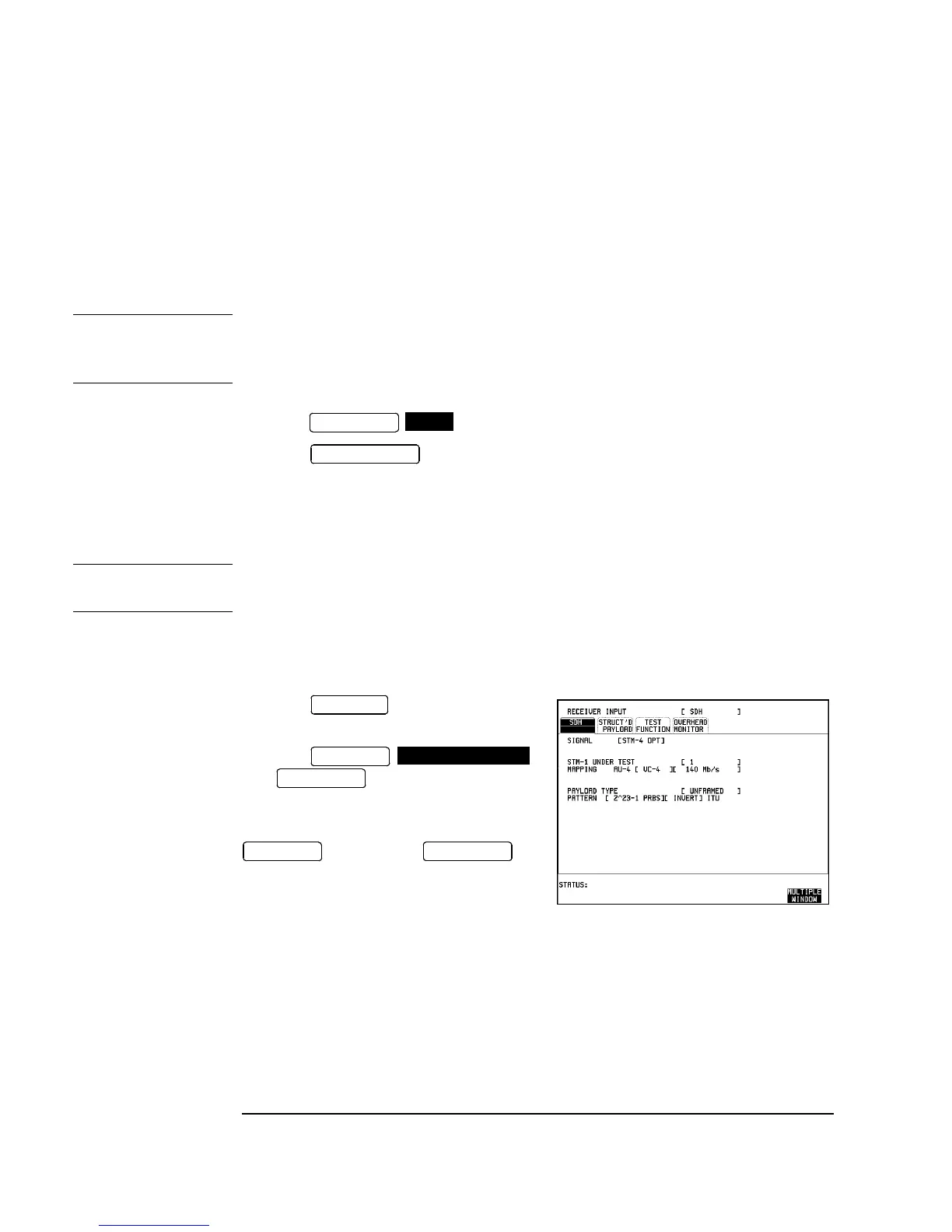
34. Press on the HP 37717C
and set up the display as shown opposite.
35. Press
then to start the measurement.
36. After 5 minutes, check that NO
TROUBLE is displayed on the HP 37717C
display.Press to
stop the measurement.
37. Recall the HP 37717C DEFAULT
SETTINGS as shown on 3-2.
38. Verify that the Optical Module LASER ON led is NOT lit indicating that the laser
is disabled before continuing.
39. Repeat steps 1 to 38 but with [STM-1 OPT] selected on the HP 37717C Tx and
Rx display parameters instead of [STM-4 OPT].
40. Disconnect all Test equipment.
TRANSMIT
SDH
AUTOSCALE
RECEIVE
RESULTS
TROUBLE SCAN
RUN/STOP
RESULTS
RUN/STOP

 Loading...


