8-182. The first of the MFC circuits described
is
the Arming multiplexer. When External Arming is enabled,
the MFC Arming multiplexer accepts an external signal from the front panel ARM input via the ARM input
(ARMI) line,
U14E pin 9. The ARMING TRIGGER LEVEL is preset to
+
1.5V by voltage-divider resistors
R21 and R22, and
is
input via the ATL line at pin 8 of U14E.
An
internal comparator level-shifts the signal to an
EECL level, and feeds this ARM OUT (ARMO) line directly to the MRC.
8-183. The second MFC circuit
is
a time base buffer. This circuit converts the ECL level 10-MHz oscillator sig-
nal to the
lTL level required to drive the oscillator input, pin 19 (OSCI) of U14B, of the MFC interpolators.
8-184. Finally, MFC U14 has two interpolators circuits
(U14B, U14C). These circuits accept the START and
STOP Interpolator pulses
(ST1 and SPI) from MRC
U20.
These pulses, which vary from 100 to 200
nanoseconds, represent the time difference (error factor) between the starting or stopping of the input signal
and the nearest 10 MHz clock pulse. To reduce this inherent one-count error by a factor of 200, the detected
error is expanded
(200X)
to a time length which can be measured by the Counter. Then, using known calibration
pulses as references, the actual error can be interpolated and the error effectively cancelled by mathematical
modifications to the raw data by Measurement MCU U29.
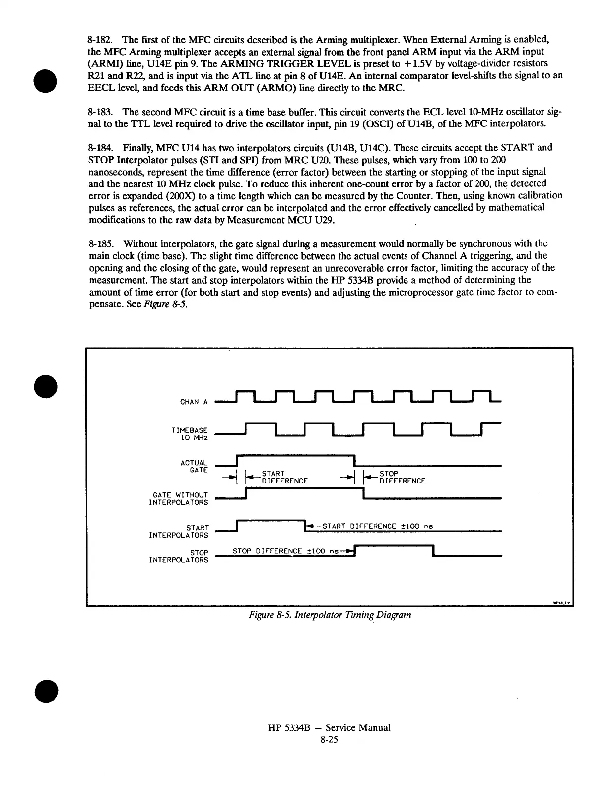
8-185. Without interpolators, the gate signal
duriig a measurement would normally be synchronous with the
main clock (time base). The slight time
difference between the actual events of Channel A triggering, and the
opening and the closing of the gate, would represent an unrecoverable error factor, limiting the accuracy of the
measurement. The start and stop interpolators within the HP
5334B provide a method of determining the
amount of time error (for both start and stop events) and adjusting the microprocessor gate time factor to com-
pensate. See
Figure
8-5.
CHAN
A
TIMEBASE
10
MHz
I
I
I
I
I I
ACTUAL
GATE
WITHOUT
INTERPOLATORS
START
START
DIFFERENCE
2100
ns
INTERPOLATORS
STOP
STOP DIFFERENCE
2100
ns
INTERPOLATORS
1
WILL9
Figure
8-5.
Interpolator Timitlg Diagram
HP
5334B
-
Service Manual
8-25