5.
Using a calibrated 10:l oscilloscope probe, connect the oscilloscope Channel A to AIR55 (A end).
NOTE
Calibrated here means simply checking the probe against the oscilloscope
front panel calibration signal. Display the calibration signal on the scope
CRT and adjust probe tuning capacitor,
if
necessary, for a correctly at-
tenuated by
10
signal.
6.
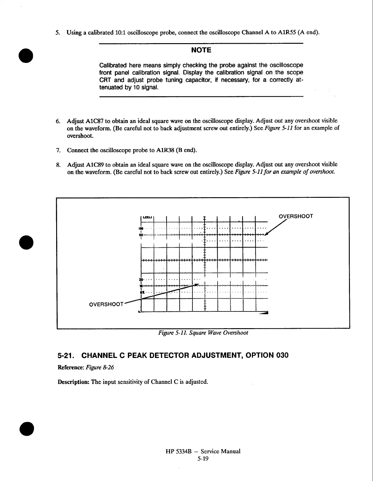
Adjust A1C87 to obtain an ideal square wave on the oscilloscope display. Adjust out any overshoot visible
on the waveform. (Be careful not to back adjustment screw out entirely.) See
Figure 5-11
for an example of
overshoot.
7.
Connect the oscilloscope probe to AIR38 (B end).
8.
Adjust AlC89 to obtain
an
ideal square wave on the oscilloscope display. Adjust out any overshoot visible
on
the waveform. (Be careful not to back screw out entirely.) See
Figure 5-11 for an evample of overshoot.
RSHOOT
OVERSHOOT
Figure 5-11. Square Wave Overshoot
5-21.
CHANNEL C PEAK DETECTOR ADJUSTMENT, OPTION
030
Reference:
Figure
8-26
Description: The input sensitivity of Channel C is adjusted.
HP
5334B
-
Service Manual
5-19