I
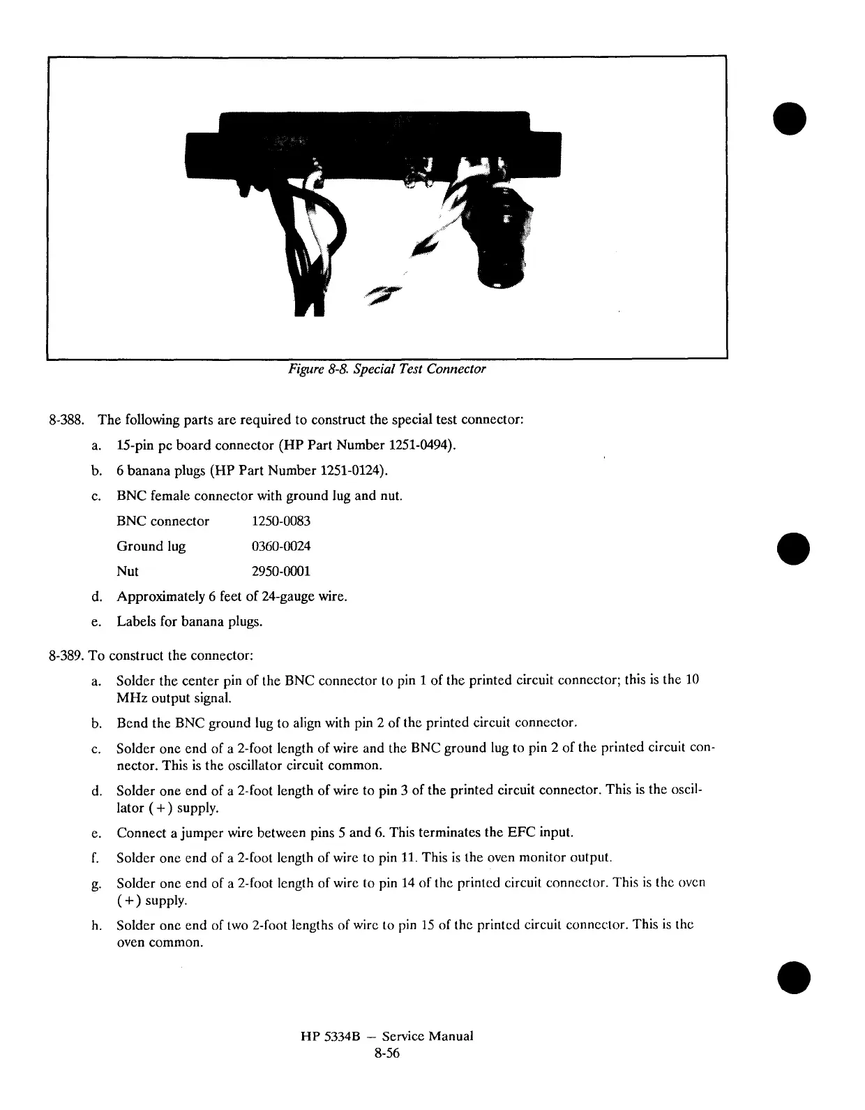
Figure
8-8.
Special Test Connector
8-388. The following parts are required to construct the special test connector:
a.
15-pin pc board connector (HP Part Number 1251-0494).
b.
6
banana plugs (HP Part Number 1251-0124).
c.
BNC female connector with ground lug and nut.
BNC connector 1250-0083
Ground lug 0360-0024
Nut 2950-0001
d. Approximately
6
feet of 24-gauge wire.
e. Labels for banana plugs.
8-389. To construct the connector:
a.
Solder the center pin of the BNC connector to pin
1
of the printed circuit connector; this is the
10
MHz output signal.
b.
Bend the BNC ground lug to align with pin 2 of the printed circuit connector.
c.
Solder one end of a 2-foot length of wire and the BNC ground lug to pin 2 of the printed circuit con-
nector. This is the oscillator circuit common.
d.
Solder one end of a 2-foot length of wire to pin
3
of the printed circuit connector. This is the oscil-
lator
(+)
supply.
e.
Connect a jumper wire between pins 5 and 6. This terminates the EFC input.
f.
Solder one end of a
Zfoot length of wire to pin
11.
This is the oven monitor output.
g.
Solder
one end of a 2-foot length of wire to pin
14
of the printed circuit connector. This is the ovcn
(
+
supply.
h.
Solder
one end of two 2-foot lengths of wire
to
pin 15 of the printed circuit connector. This
is
thc
oven common.
HP
5334B
-
Service Manual
8-56