Model 7475A
Section II
SECTION II
OPERATING AND PERFORMANCE TEST
2-1.
INTRODUCTION
2-2.
The
following
information
is provided to determine
whether
the
plotter is
operating
properly.
If
operation
is
not
correct,
refer
to Section VI
of
this
manual
for service
information.
2-3. REAR PANEL SWITCHES (Option 001)
2-4.
A3/
A4.
This
switch
chooses between
Bl
A3 size
paper
and
A/
A4 size paper.
The
switch
is used to
set
the
default
paper
size
only
at
power up.
Subsequent
paper
size
changes
can
be
made
from
the
front
panel.
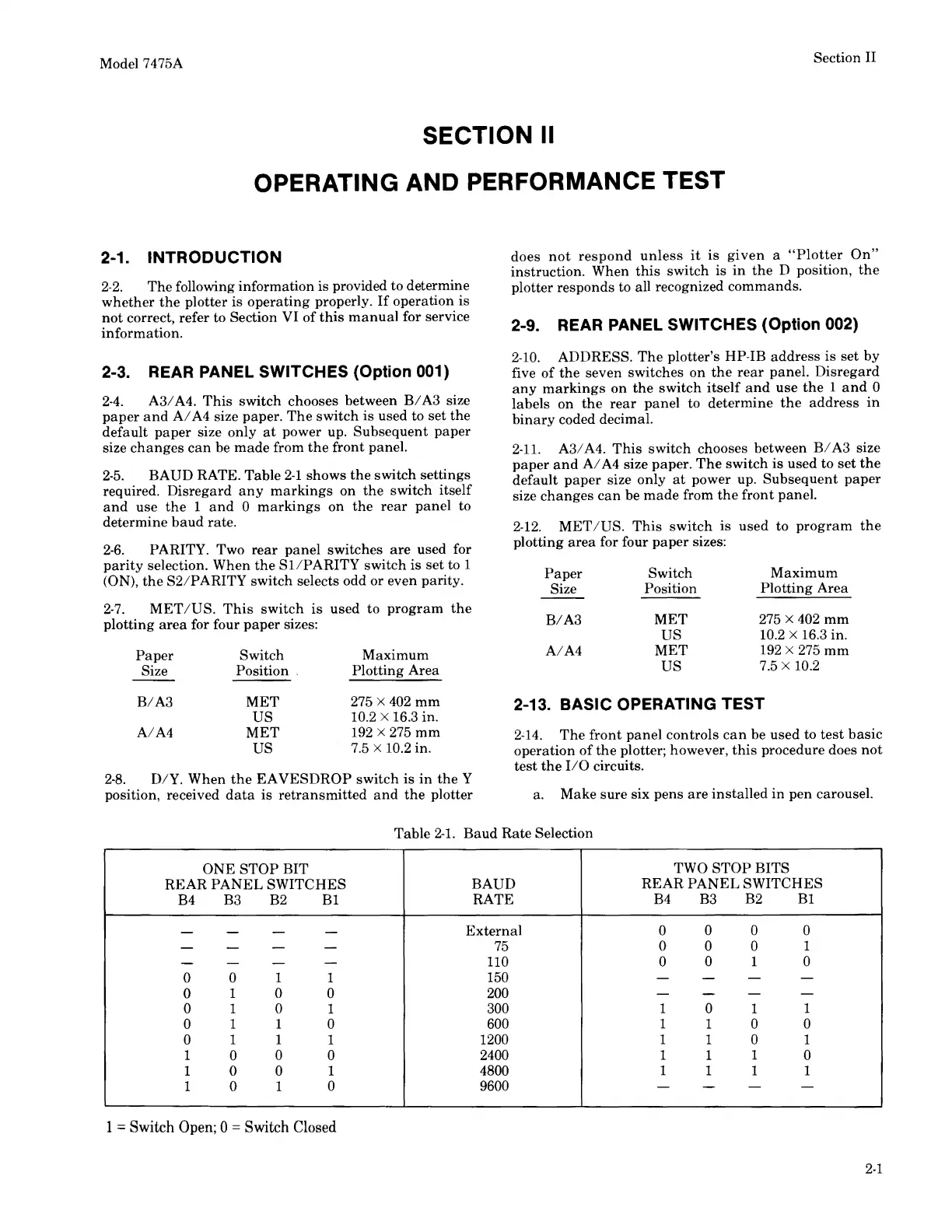
2-5.
BAUD
RATE. Table
2-1
shows
the
switch
settings
required.
Disregard
any
markings
on
the
switch
itself
and
use
the
1
and
0
markings
on
the
rear
panel
to
determine
baud
rate.
2-6.
PARITY. Two
rear
panel
switches
are
used for
parity
selection.
When
the
SI/PARITY
switch
is
set
to 1
(ON),
the
S2/PARITY
switch
selects odd or even parity.
2-7.
MET/US.
This
switch
is
used
to
program
the
plotting
area
for four
paper
sizes:
Paper
Switch
Maximum
Size
Position
.
Plotting
Area
B/A3
MET
275 x 402
mm
us
10.2 x 16.3 in.
A/A4
MET
192 x 275
mm
us
7.5 x 10.2 in.
2-8.
D/Y.
When
the
EAVESDROP
switch
is
in
the
Y
position, received
data
is
retransmitted
and
the
plotter
does
not
respond
unless
it
is
given
a
"Plotter
On"
instruction.
When
this
switch
is
in
the
D position,
the
plotter responds to all recognized
commands.
2-9. REAR PANEL SWITCHES (Option 002)
2-10.
ADDRESS.
The
plotter's HP-IB
address
is
set
by
five
of
the
seven
switches
on
the
rear
panel.
Disregard
any
markings
on
the
switch
itself
and
use
the
1
and
0
labels
on
the
rear
panel
to
determine
the
address
in
binary
coded decimal.
2-11.
A3/
A4.
This
switch
chooses between
Bl
A3 size
paper
and
A/
A4 size
paper.
The
switch
is
used
to
set
the
default
paper
size
only
at
power up.
Subsequent
paper
size
changes
can
be
made
from
the
front
panel.
2-12.
MET
/US.
This
switch
is
used
to
program
the
plotting
area
for four
paper
sizes:
Paper
Switch
Maximum
Size
Position
Plotting
Area
BIA3
MET
275 x 402
mm
us
10.2 X 16.3 in.
A/A4
MET
192 X 275
mm
us
7.5 x 10.2
2-13. BASIC OPERATING TEST
2'14.
The
front
panel
controls
can
be
used
to
test
basic
operation
of
the
plotter; however,
this
procedure does
not
test
the
110 circuits.
a.
Make
sure
six
pens
are
installed
in
pen
carousel.
Table
2-1.
Baud
Rate
Selection
ONE
STOP
BIT
TWO
STOP
BITS
REAR
PANEL
SWITCHES
BAUD
REAR
PANEL
SWITCHES
B4 B3
B2
Bl
RATE
B4 B3
B2
Bl
-
- - -
External
0
0 0 0
-
- - -
75
0 0 0
1
-
-
-
-
110 0
0 1 0
0 0
1
1
150
- -
- -
0
1 0
0
200
-
-
- -
0 1 0
1
300 1 0 1
1
0
1 1
0
600 1 1 0 0
0
1 1
1
1200 1 1 0 1
1
0
0
0
2400 1 1
1
0
1 0 0 1 4800
1 1 1 1
1 0 1 0
9600 -
-
- -
1 = Switch Open; 0 = Switch Closed
2-1