Section
VI
6-58.
TROUBLESHOOTING TABLE
6-59.
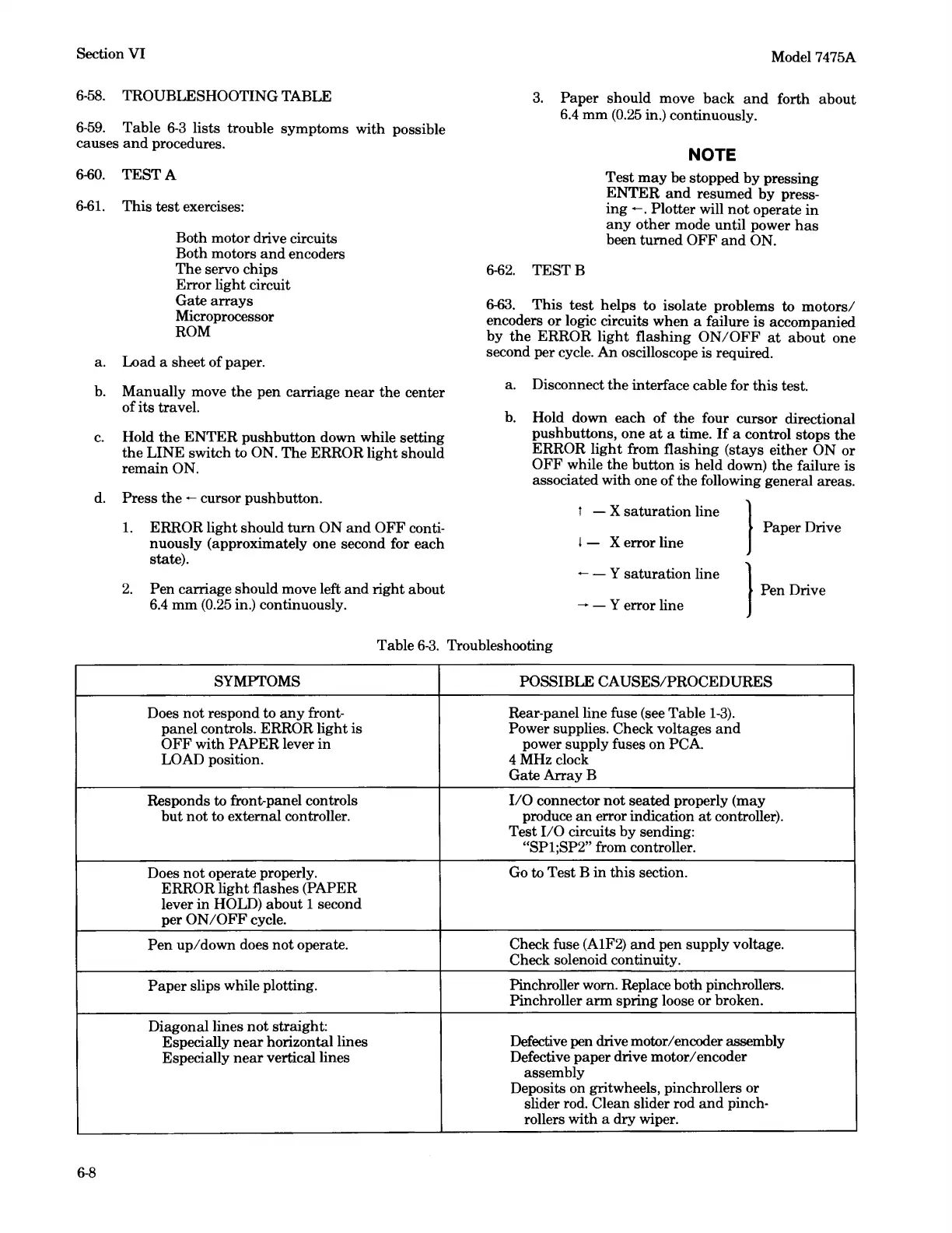
Table
6-3
lists trouble symptoms with possible
causes
and
procedures.
6-60.
TEST
A
6-61.
This
test
exercises:
Both motor drive circuits
Both motors
and
encoders
The
servo chips
Error
light circuit
Gate
arrays
Microprocessor
ROM
a. Load a sheet of paper.
b.
Manually move
the
pen carriage
near
the center
of its travel.
c.
Hold
the
ENTER
pushbutton down while setting
the
LINE
swit.ch to ON.
The
ERROR light should
remain ON.
d. Press
the
- cursor pushbutton.
1.
ERROR light should turn
ON
and
OFF
conti-
nuously (approximately one second for each
state).
2.
Pen carriage should move left
and
right about
6.4
mm
(0.25
in.) continuously.
Model 7475A
3.
Paper should move back
and
forth about
6.4
mm
(0.25
in.) continuously.
6-62.
TESTB
NOTE
Test
may
be stopped
by
pressing
ENTER
and
resumed
by
press-
ing
- . Plotter will
not
operate
in
any
other mode until power
has
been turned
OFF
and
ON.
6-63.
This
test
helps to isolate problems to
motors/
encoders
or
logic circuits when a failure
is
accompanied
by
the
ERROR
light
flashing
ON/OFF
at
about one
second per cycle. An oscilloscope is required.
a. Disconnect
the
interface cable for this test.
b.
Hold down each
of
the
four cursor directional
pushbuttons, one
at
a time.
If
a control stops
the
ERROR
light
from flashing (stays either
ON
or
OFF
while
the
button
is
held down)
the
failure
is
associated with one
of
the following general areas.
t - X saturation line }
Paper Drive
I - X error line
- - Y saturation line
}
Pen
Drive
- - Y error line
Table
6-3.
Troubleshooting
SYMPTOMS POSSIBLE CAUSES/PROCEDURES
Does
not
respond to
any
front- Rear-panel line fuse (see Table
1-3).
panel controls. ERROR light
is
Power supplies. Check voltages
and
OFF
with
PAPER
lever
in
power supply fuses on
PCA
LOAD position.
4MHzclock
GateArrayB
Responds to front-panel controls
I/O
connector
not
seated properly (may
but
not
to external controller. produce
an
error indication
at
controller).
Test
I/O
circuits
by
sending:
"SP1;SP2" from controller.
Does
not
operate properly.
Go
to Test B in this section.
ERROR light flashes (PAPER
lever
in
HOLD) about 1 second
per
ON/OFF
cycle.
Pen
up/down
does
not
operate.
Check fuse (A1F2)
and
pen supply voltage.
Check solenoid continuity.
Paper
slips while plotting.
Pinchroller worn. Replace both pinchrollers.
Pinchroller
arm
spring loose or broken.
Diagonal lines
not
straight:
Especially
near
horizontal lines
Defective pen drive motor/encoder assembly
Especially
near
vertical lines
Defective paper drive motor/encoder
assembly
Deposits on gritwheels, pinchrollers or
slider rod. Clean slider rod
and
pinch-
rollers with a dry wiper.
6-8