Model 7475A
COUPLER
RING
PAPER
DRIVE
SHAFT
COUPLER
7475-A-21-1
Section VI
MOTOR
SHAFT
COUPLER
RUBBER
0-RINGS
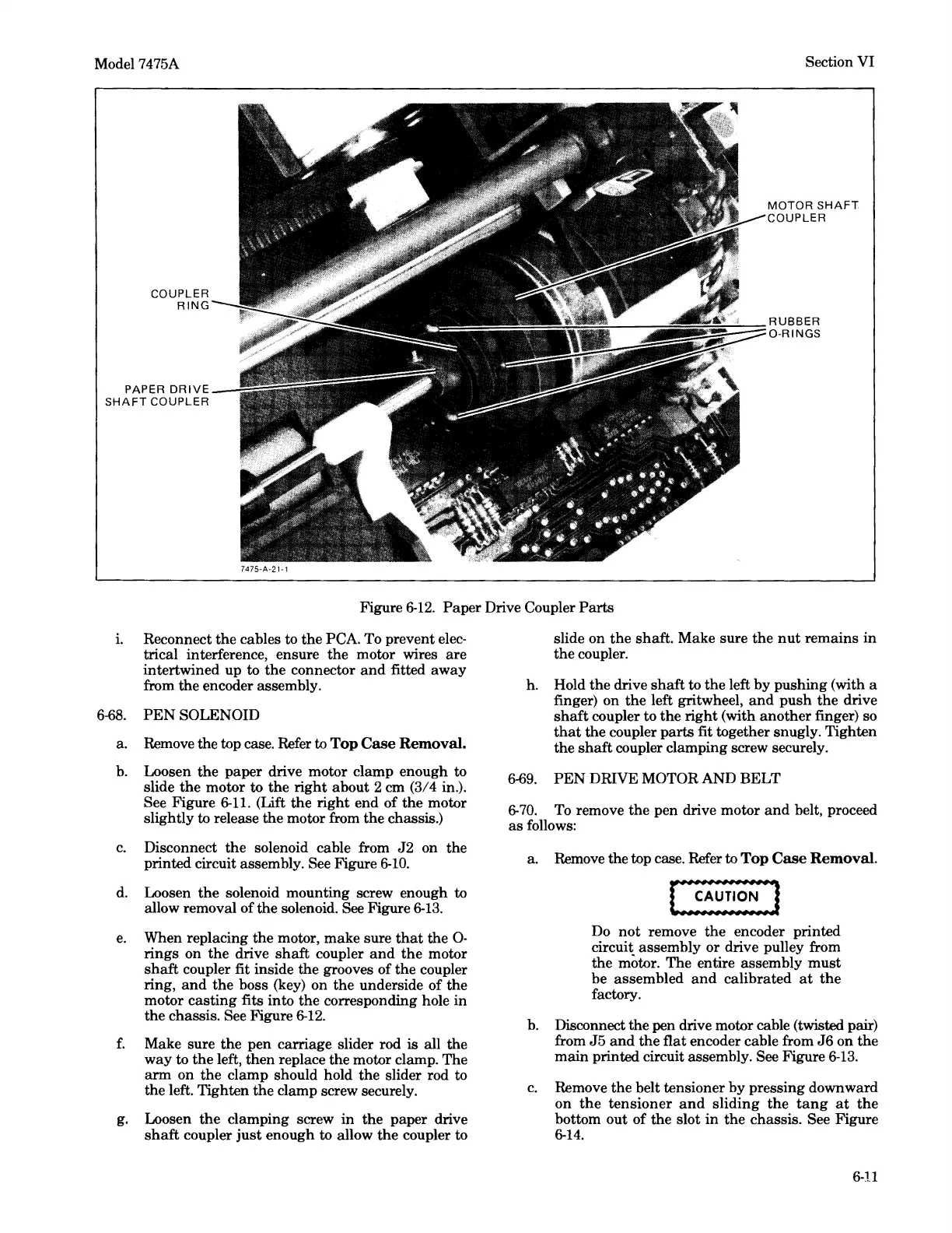
Figure
6-12.
Paper
Drive Coupler
Parts
i. Reconnect
the
cables to
the
PCA. To prevent elec-
trical interference, ensure the motor wires
are
intertwined up to
the
connector
and
fitted
away
from the encoder assembly.
6-68.
PEN
SOLENOID
a. Remove the top case. Refer to Top
Case
Removal.
b.
Loosen
the
paper
drive motor clamp enough to
slide
the
motor to
the
right
about 2 cm (3/4 in.).
See Figure
6-11.
(Lift
the
right
end
of
the
motor
slightly to release
the
motor from
the
chassis.)
c.
Disconnect
the
solenoid cable from
J2
on the
printed circuit assembly. See Figure
6-10.
d. Loosen
the
solenoid mounting screw enough to
allow removal of the solenoid. See Figure
6-13.
e.
When replacing the motor, make sure
that
the
0-
rings
on
the
drive
shaft
coupler
and
the
motor
shaft
coupler fit inside the grooves of the coupler
ring,
and
the
boss (key) on
the
underside
of
the
motor
casting
fits into the corresponding hole in
the chassis. See Figure
6-12.
f.
Make sure
the
pen
carriage slider rod
is
all the
way
to
the
left, then replace the motor clamp. The
arm
on the clamp should hold the slider rod to
the left. Tighten
the
clamp screw securely.
g. Loosen
the
clamping screw
in
the
paper drive
shaft
coupler
just
enough to allow
the
coupler to
slide on
the
shaft.
Make sure
the
nut
remains
in
the coupler.
h. Hold
the
drive
shaft
to
the
left
by
pushing (with a
finger) on
the
left gritwheel,
and
push
the
drive
shaft
coupler to
the
right
(with
another
finger) so
that
the coupler
parts
fit together snugly. Tighten
the
shaft
coupler clamping screw securely.
6-69.
PEN
DRIVE MOTOR AND BELT
6-
70.
To remove
the
pen drive motor
and
belt, proceed
as
follows:
a. Remove the top case. Refer to Top
Case
Removal.
Do
not
remove
the
encoder printed
circuit assembly
or
drive pulley from
the motor. The entire assembly
must
be assembled
and
calibrated
at
the
factory.
b.
Disconnect the pen drive motor cable (twisted pair)
from
J5
and
the flat encoder cable from
J6
on
the
main
printed circuit assembly. See Figure
6-13.
c.
Remove
the
belt tensioner
by
pressing downward
on
the
tensioner
and
sliding
the
tang
at
the
bottom
out
of
the slot
in
the
chassis. See Figure
6-14.
6-U