Section VI
7475-A-25-1
PEN
DOWN
SPRING
Figure
6-16.
Measuring Pen Down Force
6-75.
PINCH
ROLLERS REMOVAL AND
REPLACEMENT
a. Remove
the
top case. Refer to
To
Case
Removal.
b. Remove
the
retaining
ring
that
secures
the
pinch
roller. See Figure
6-17.
PINCH
ROLLERS
Figure
6-17.
Pinch Rollers
c.
Remove
the
pinch roller.
d. Replace
the
pinch roller.
The
larger
diameter
end
of
the
pinch roller
must
be toward
the
outer edge
of
the
plotting surface.
This
is
necessary to keep
the
plotting media
in
place.
e.
Replace
the
retaining ring.
f.
Replace
the
pen carousel
and
top case making sure
the
PAPER
LOAD/HOLD lever extends through
the
case
and
the
tabs
inside
the
front
of
the
case
are
aligned properly above
and
below
the
base
plate.
6-14
Model 7475A
6-76.
PRINTED
CffiCUIT ASSEMBLY REMOVAL
a. Remove
the
top case. Refer to
Top
Case
Removal.
b.
Disconnect
all
cables from
the
printed
circuit
assembly.
c.
Remove
the
pen
carousel housing. Refer to
Pen
Carousel
Housing
Removal.
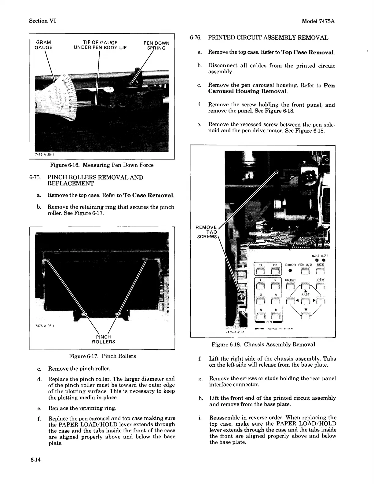
d.
Remove
the
screw holding
the
front panel,
and
remove
the
panel. See Figure
6-18.
e.
Remove the recessed screw between
the
pen
sole-
noid
and
the
pen drive motor. See Figure
6-18.
REMOVE
TWO
SCREWS
Figure
6-18.
Chassis
Assembly Removal
f.
Lift
the
right
side of
the
chassis
assembly.
Tabs
on
the
left side will release from the
base
plate.
g.
Remove
the
screws or studs holding
the
rear
panel
interface connector.
h. Lift
the
front
end
of
the
printed circuit assembly
and
remove from
the
base plate.
L Reassemble
in
reverse order. When replacing
the
top case,
make
sure
the
PAPER
LOAD/HOLD
lever extends
through
the
case
and
the
tabs
inside
the
front
are
aligned properly above
and
below
the
base
plate.