Section VI
c.
Remove
the
screw
that
secures
the
pen carousel
housing
to
the
chassis
assembly. See Figure
6-9.
PEN
CAROUSEL
HOUSING
PEN
CAROUSEL
PEN
CAROUSEL
HOUSING
SCREW
7475-A-18-1
Figure
6-9.
Pen
Carousel Housing
d.
Tip
the
pen carousel
housing
forward
and
lift
straight
up
being careful
not
to
catch
the
cable
connector on
the
chassis
assembly.
e.
To reassemble, reverse steps a.
through
d.
6-67.
PAPER
DRIVE MOTOR ASSEMBLY
REMOVAL
a. Remove the top case. Refer to
Top
Case
Removal.
Do
not
remove
the
encoder
printed
circuit
assembly
or
the
drive coupler
from
the
motor.
The
entire
unit
must
be
assembled
and
calibrated
at
the
factory.
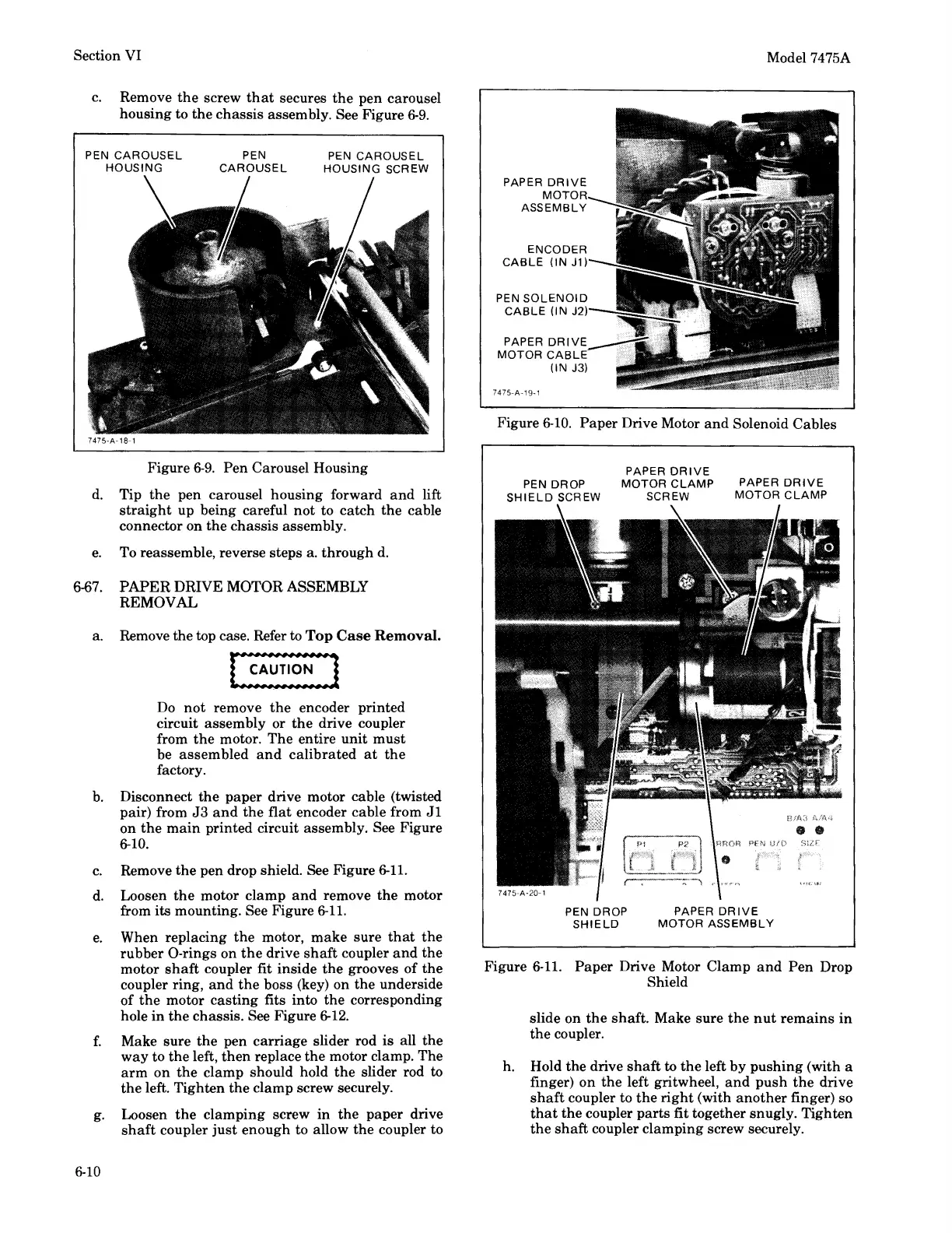
b.
Disconnect
the
paper
drive motor cable (twisted
pair) from
J3
and
the
flat
encoder cable from
Jl
on
the
main
printed circuit assembly. See Figure
6-10.
c.
Remove
the
pen drop shield. See Figure
6-11.
d.
Loosen
the
motor
clamp
and
remove
the
motor
from its mounting. See Figure
6-11.
e.
When replacing
the
motor,
make
sure
that
the
rubber
0-rings
on
the
drive
shaft
coupler
and
the
motor
shaft
coupler fit
inside
the
grooves
of
the
coupler ring,
and
the
boss (key) on
the
underside
of
the
motor
casting
fits into
the
corresponding
hole
in
the
chassis. See Figure
6-12.
f.
Make
sure
the
pen
carriage
slider rod
is
all
the
way
to
the
left,
then
replace
the
motor clamp.
The
arm
on
the
clamp
should hold
the
slider rod to
the
left. Tighten
the
clamp
screw securely.
g.
Loosen
the
clamping
screw
in
the
paper
drive
shaft
coupler
just
enough
to allow
the
coupler to
6-10
PAPER
DRIVE
MOTOR
ASSEMBLY
ENCODER
CABLE
(IN
J1)
PEN
SOLENOID
CABLE
(IN J2)
PAPER
DRIVE
MOTOR
CABLE
(IN J3)
7475-A-19-1
Model 7475A
Figure
6-10.
Paper
Drive Motor
and
Solenoid Cables
PAPER
DRIVE
PEN DROP
MOTOR
CLAMP
PAPER
DRIVE
SHIELD
SCREW SCREW
MOTOR
CLAMP
PEN DROP
SHIELD
B/A~l
AIA4
••
PEN
s1zr
PAPER
DRIVE
MOTOR
ASSEMBLY
Figure
6-11.
Paper
Drive Motor
Clamp
and
Pen
Drop
Shield
slide on
the
shaft.
Make
sure
the
nut
remains
in
the
coupler.
h. Hold
the
drive
shaft
to
the
left
by
pushing
(with a
finger)
on
the
left gritwheel,
and
push
the
drive
shaft
coupler
to
the
right
(with
another
finger) so
that
the
coupler
parts
fit together snugly.
Tighten
the
shaft
coupler
clamping
screw securely.