Section VI
i.
Hold
the
drive
shaft
to
the
left by
pushing
(with a
finger)
on
the
left gritwheel,
and
push
the
drive
shaft
coupler to
the
right
(with
another
finger) so
that
the
coupler
parts
fit together snugly.
Tighten
the
shaft
coupler
clamping
screw securely.
j. Replace all
parts
in
reverse order.
6-80.
POWER
MODULE AND
TRANSFORMER
a. Remove
the
top case. Refer to
Top
Case
Removal.
b.
Remove
the
chassis
assembly. Refer to
Printed
Circuit
Assembly
Removal,
steps
b.
through
f.
NOTE
The
transformer
is
held
in
place by
the
power module molding.
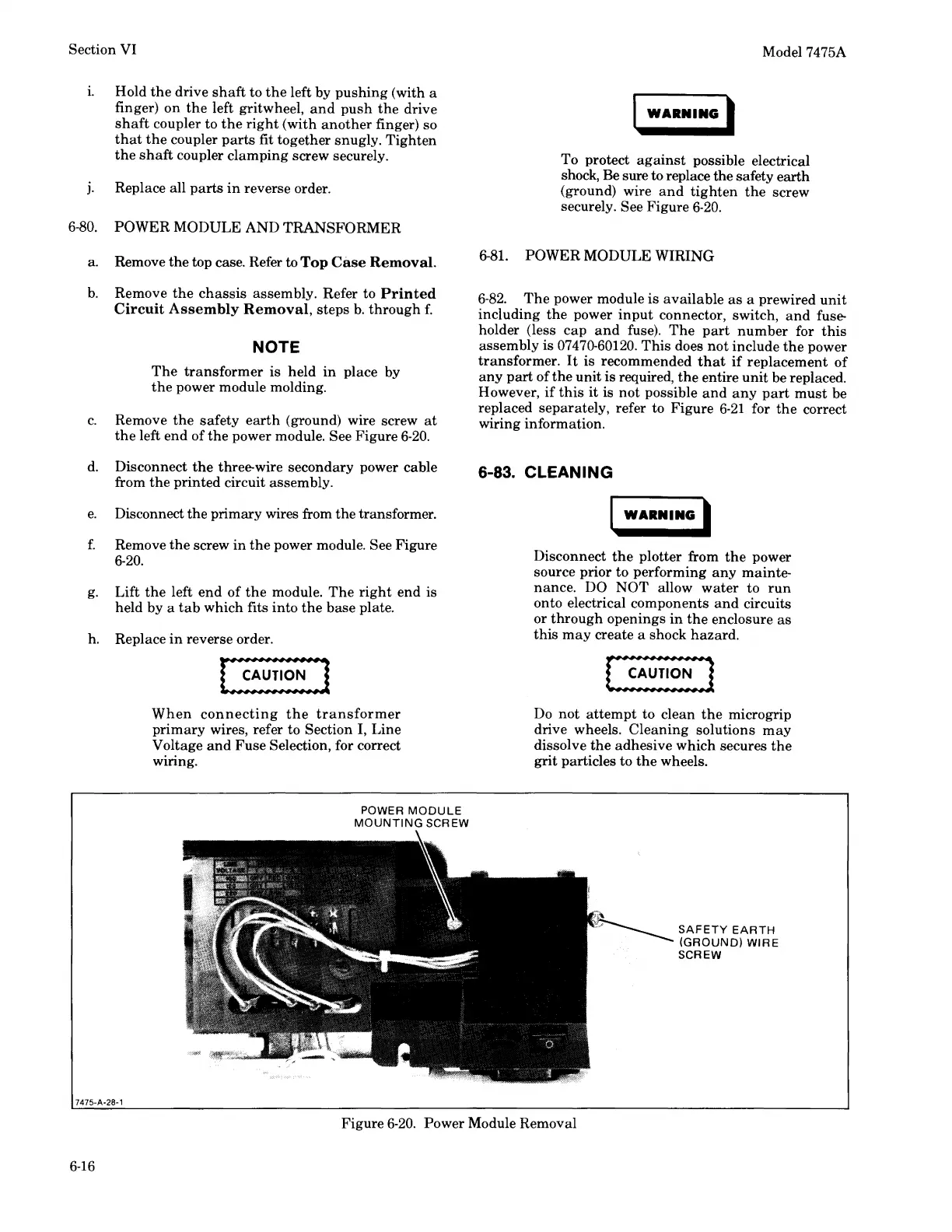
c.
Remove
the
safety
earth
(ground) wire screw
at
the
left end of
the
power module. See Figure
6-20.
d. Disconnect
the
three-wire secondary power cable
from
the
printed circuit assembly.
e.
Disconnect the primary wires from the transformer.
f.
Remove
the
screw
in
the
power module. See Figure
6-20.
g.
Lift
the
left
end
of
the
module.
The
right
end is
held by a
tab
which fits
into
the
base
plate.
h.
Replace
in
reverse order.
7475·A·28·1
When
connecting
the
transformer
primary
wires, refer to Section I, Line
Voltage
and
Fuse
Selection, for correct
wiring.
POWER
MODULE
MOUNTING
SCREW
Model 7475A
WARNING'
To protect
against
possible electrical
shock, Be sure
to
replace the safety
earth
(ground) wire
and
tighten
the
screw
securely. See Figure
6-20.
6-81.
POWER
MODULE
WIRING
6-82.
The
power module
is
available
as
a prewired
unit
including
the
power
input
connector, switch,
and
fuse-
holder (less
cap
and
fuse).
The
part
number
for
this
assembly is 07470-60120.
This
does
not
include
the
power
transformer.
It
is
recommended
that
if
replacement
of
any
part
of
the
unit
is
required,
the
entire
unit
be replaced.
However,
if
this
it
is
not
possible
and any
part
must
be
replaced separately, refer to Figure
6-21
for
the
correct
wiring information.
6-83. CLEANING
WARNING I
Disconnect
the
plotter from
the
power
source prior
to
performing
any
mainte-
nance. DO
NOT
allow
water
to
run
onto electrical components
and
circuits
or
through
openings
in
the
enclosure
as
this
may
create a shock
hazard.
Do
not
attempt
to clean
the
microgrip
drive wheels.
Cleaning
solutions
may
dissolve
the
adhesive
which
secures
the
grit
particles
to
the
wheels.
r'\
;~SAFETY
EARTH
(GROUND)
WIRE
SCREW
Figure
6-20.
Power Module Removal
6-16