Model
7475A
Section III
SECTION Ill
ADJUSTMENTS
3-1. INTRODUCTION
3-2.
This section describes mechanical adjustments
required to return the
HP
7475A
to its nonnal operating
condition after repairs have been made. There are no
electrical adjustments in the
HP
7475A.
3-3. EQUIPMENT REQUIRED
3-4.
The adjustment procedures require use of the
fol-
lowing tools:
Allen wrench
(0.050
in.)
100
mm ruler
3-5. MECHANICAL ADJUSTMENTS
3-6.
PEN
HEIGHT ADJUSTMENT
3-7.
Pen
height adjustment is necessary
if
the pen
carriage assembly is disassembled or replaced.
I WARNING I
The following procedure should be per-
onned only
by
service-trained personnel
who are aware of the electrical shock
hazards involved.
a. Set the
HP
7475A LINE switch to
OFF
(0)
and
disconnect the line cord.
b.
Remove
the
HP
7475A top case by removing the
screws indicated
in
Figure
3-1.
REMOVE THREE
SCREWS
Figure
3-1.
Top Case Removal
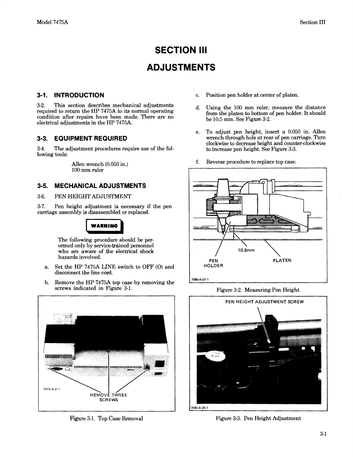
c.
Position pen holder
at
center of platen.
d.
Using the
100
mm ruler, measure the distance
from the platen to bottom of pen holder.
It
should
be
10.5
mm. See Figure
3-2.
e.
To adjust pen height, insert a
0.050
in. Allen
wrench through hole
at
rear
of pen carriage. Turn
clockwise to decrease height
and
counter-clockwise
to increase pen height. See Figure
3-3.
f.
Reverse procedure to replace top case.
PEN
HOLDER
PLATEN
Figure
3-2.
Measuring
Pen
Height
PEN
HEIGHT
ADJUSTMENT
SCREW
7090-A-25· 1
Figure
3-3.
Pen
Height Adjustment
3-1