Section VI
00
01
02
03
I
1
STOP-I
(7 .5°)
7475-A-15-1
I I I I I
L30msecj
(a)
CW
SEQUENCE
00
01
02
03
Model 7475A
(b) CCW SEQUENCE
Figure
6-4.
Quadrature Waveforms
r
ENCA
FROM
PROCESSOR DEC
SERVO ENC B
THROUGH
IC
GATE
ARRAY
X
2
X4
SIGN
SERVO
CONDITION
MOTOR
._
OPTICAL
PULSE
CIRCUIT
DRIVERS
__.
ENCODER
(PART OF
GATE
ARRAY)
STRETCHED
PULSE
PULSE
WIDTH
=>
DIGITAL
DATA
FROM
GAIN
ADJUST
+18/26V
PROCESSOR
(PART
OF
UNREGULATED
GATE
ARRA
YI
7470-A-15-1
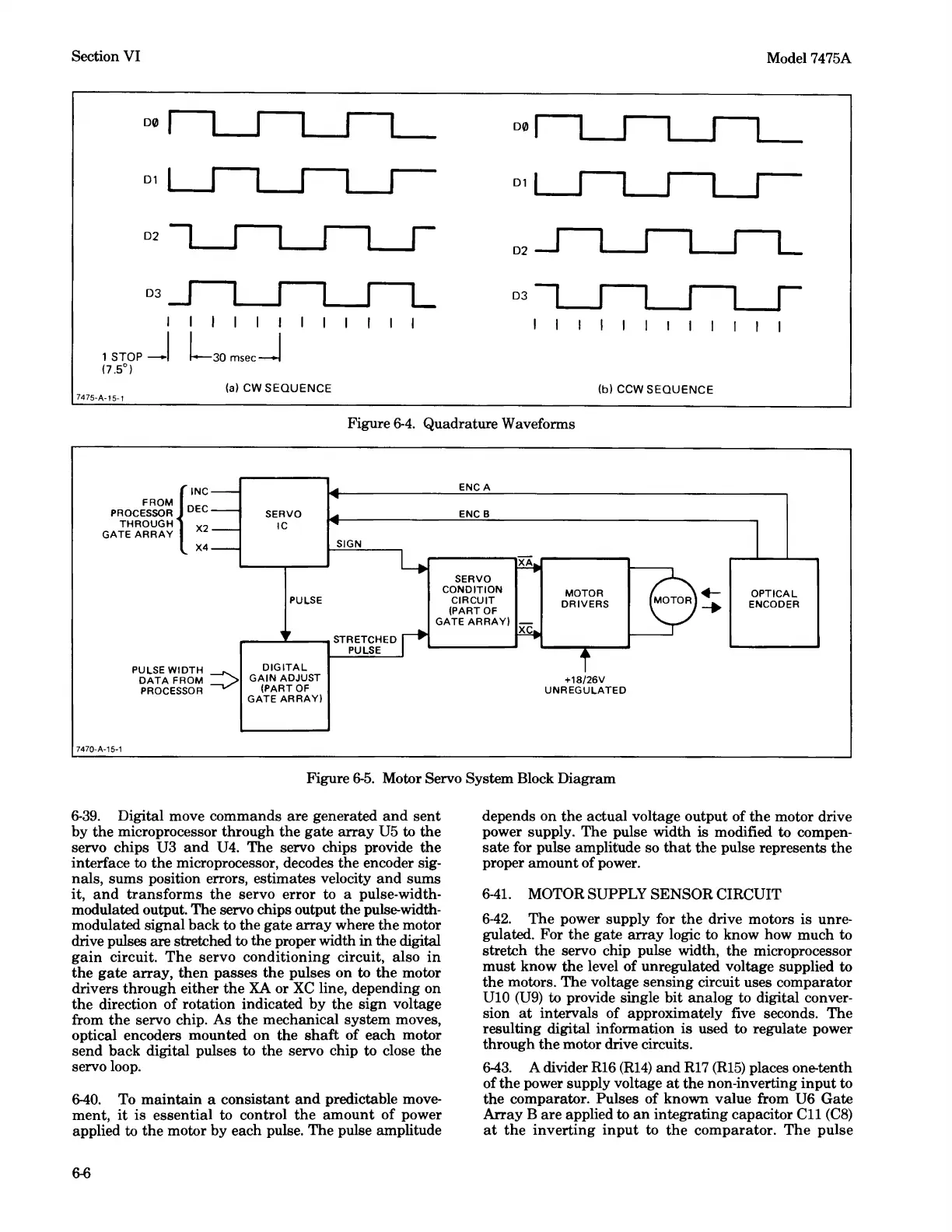
Figure
6-5.
Motor Servo System Block Diagram
6-39.
Digital move commands are generated
and
sent
by
the
microprocessor through
the
gate
array
U5 to
the
servo chips U3
and
U4. The servo chips provide
the
interface to the microprocessor, decodes the encoder sig-
nals, sums position errors, estimates velocity
and
sums
it,
and
transforms
the
servo error to a pulse-width-
modulated output. The servo chips output
the
pulse-width-
modulated signal back to
the
gate
array
where
the
motor
drive pulses are stretched to the proper width
in
the digital
gain
circuit.
The
servo conditioning circuit, also
in
the
gate
array,
then
passes
the
pulses on to
the
motor
drivers through either
the
XA
or
XC
line, depending on
the direction of rotation indicated by the sign voltage
from
the
servo chip. As the mechanical system moves,
optical encoders mounted on
the
shaft
of each motor
send hack digital pulses to
the
servo chip to close the
servo loop.
6-40.
To
maintain
a consistant
and
predictable move-
ment,
it
is essential to control
the
amount
of power
applied to the motor by each pulse. The pulse amplitude
6-6
depends on
the
actual voltage output of
the
motor drive
power supply. The pulse width is modified to compen-
sate
for pulse amplitude so
that
the
pulse represents
the
proper amount of power.
6-41.
MOTOR SUPPLY SENSOR CIRCUIT
6-42.
The
power supply for
the
drive motors
is
unre-
gulated. For
the
gate
array
logic to know how much to
stretch the servo chip pulse width,
the
microprocessor
must
know
the
level of unregulated voltage supplied to
the
motors.
The
voltage sensing circuit uses comparator
UlO
(U9)
to provide single bit analog to digital conver-
sion
at
intervals of approximately five seconds. The
resulting digital information
is
used to regulate power
through
the
motor drive circuits.
6-43.
A divider
R16
(R14)
and
Rl
7
(R15)
places one-tenth
of
the
power supply voltage
at
the
non-inverting
input
to
the
comparator. Pulses of known value from U6 Gate
Array B are applied to
an
integrating capacitor
C11
(C8)
at
the
inverting
input
to
the
comparator.
The
pulse