Model 7475A
1/0
7475-A-13-1A
LINE
DRIVERS/
DS~~A
6
READY
CLitR
5
SEND
L~NEgl~~~L
8
DETECTOR
TE~~i~AL
20
READY
RECEIVED
3
DATA
s~~~~~~~Y16
DATA
RECEIVERS
0
0
0
0
REQUEST~
TO
SEND
'--...J
'\/
FA
07
FA
06
FA
05
FA
04
5
EI00
Section VI
INTERNAL
DATA
BUS
ACIA
Rrs
R/W
13
R
EAD/iiVRITE
E
14
1
MHz
2
RXD
3
RX
CLK
BAUD
RATE
TX
CLK
4
CLOCK
11
A6
A13
CS1
10
A15
CS0
8
VMA
15
07
U13
16
06
17
05
6
TXD
18
04
INTERNAL
19
DJ
DATA
BUS
20
02
21
01
22
00
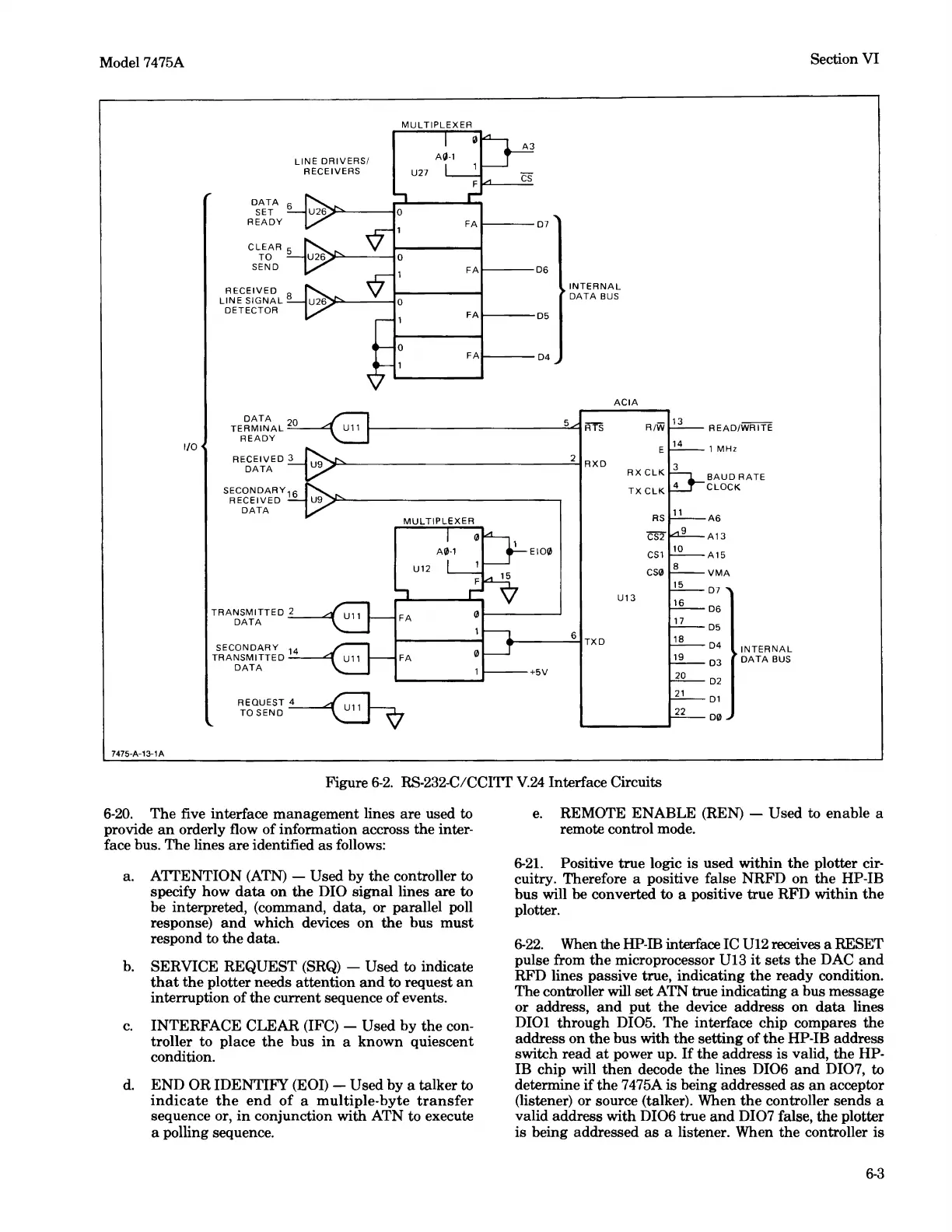
Figure
6-2.
RS-232-C/CCITT
V.24
Interface Circuits
6-20.
The five interface management lines are used to
provide
an
orderly flow of information accross the inter-
face bus. The lines are identified
as
follows:
a. ATTENTION
(ATN)
- Used by the controller to
specify how
data
on
the
DIO signal lines are to
be interpreted, (command, data, or parallel poll
response)
and
which devices on
the
bus
must
respond to
the
data.
b.
SERVICE REQUEST
(SRQ)
- Used to indicate
that
the
plotter needs attention
and
to request
an
interruption of the current sequence of events.
c.
INTERFACE CLEAR (IFC) - Used by the con-
troller to place
the
bus
in
a known quiescent
condition.
d.
END OR IDENTIFY (EOI) - Used by a talker to
indicate
the
end
of
a multiple-byte
transfer
sequence or,
in
conjunction with ATN to execute
a polling sequence.
e.
REMOTE ENABLE (REN) - Used to enable a
remote control mode.
6-21.
Positive true logic
is
used within
the
plotter cir-
cuitry. Therefore a positive false NRFD on
the
HP-IB
bus will
be
converted to a positive true RFD within
the
plotter.
6-22.
When the HP-IB interface IC
U12
receives a RESET
pulse from
the
microprocessor U13
it
sets
the
DAC
and
RFD lines passive true, indicating
the
ready condition.
The controller will set ATN true indicating a bus message
or address,
and
put
the
device address on
data
lines
DIOI through DI05. The interface chip compares the
address on
the
bus with the setting of
the
HP-IB address
switch read
at
power up.
If
the
address
is
valid, the HP-
IB chip will
then
decode
the
lines
DI06
and
DI07, to
determine
ifthe
7475A is being addressed
as
an
acceptor
(listener) or source (talker). When
the
controller sends a
valid address with
DI06
true
and
DI07
false, the plotter
is being addressed
as
a listener. When the controller is
6-3