Note
Refer to the guidelines in
Table
4-l when measuring a signal with signal delay.
To use
Table
4-4 and Table 4-5:
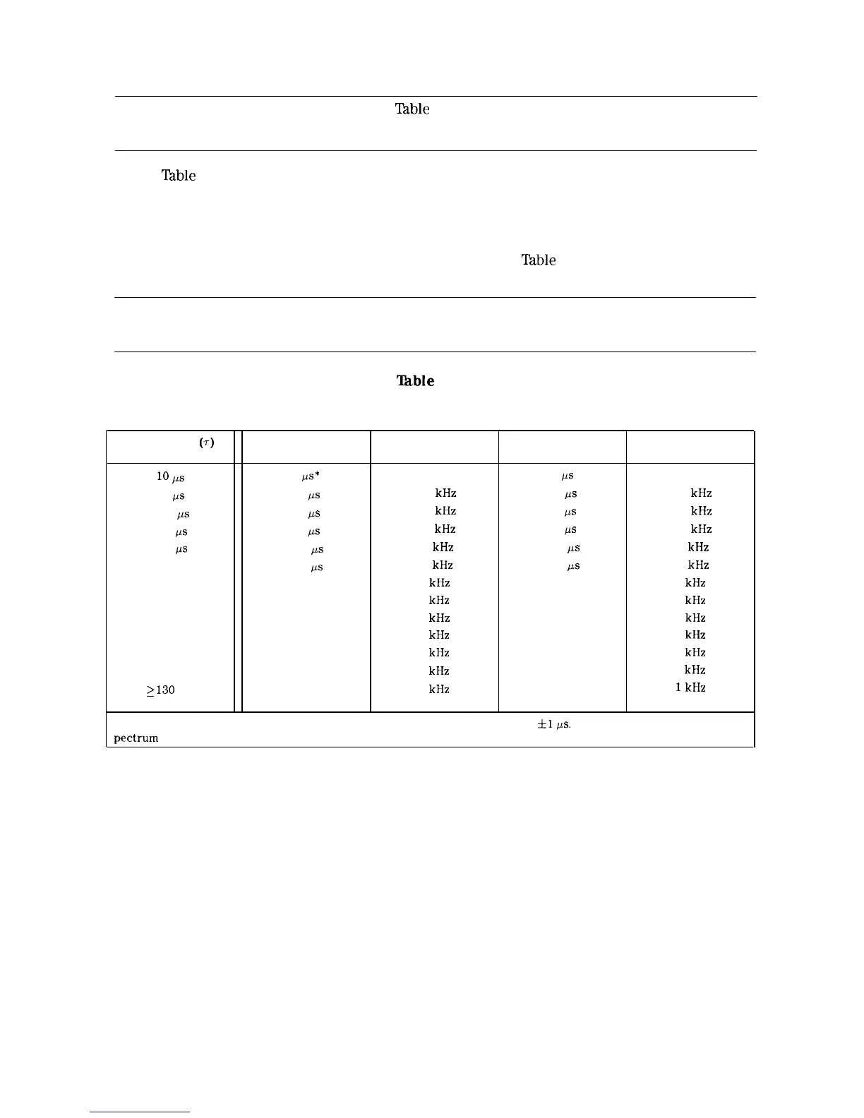
n Determine the pulse width of the signal you want to measure, then use Table 4-4 to
determine the gate delay, resolution bandwidth, gate length, and video bandwidth spectrum
analyzer settings.
n Determine the pulse repetition rate of the signal, then use
‘fable
4-5 to determine the
spectrum analyzer sweep-time setting.
Note
The peak detection mode is recommended for making gated measurements.
‘able
4-4.
Gate
Delay, Resolution Bandwidth, Gate Length, and Video Bandwidth
Settings
Pulse width
(7)
10
ps
50
ps
63.5
ps
100
ps
500
!.a
1 ms
5 ms
10 ms
16.6 ms
33 ms
50 ms
100 ms
2130 ms
Gate
Delay
5
/As*
25
ps
32
/IS
50
ps
250
ps
500
ps
2.5 ms
5 ms
8.3 ms
16.5 ms
25 ms
50 ms
65 ms
Resolution
Bandwidth
1 MHz
100 kHz
100
kHz
100
kHz
10
kHz
10 kHz
1 kHz
1
kHz
1
kHz
1
kHz
1
kHz
1
kHz
1
kHz
Gate
Length
3
/Is
13
&s
16
fis
25
ps
125
ps
250
ps
1.25 ms
2.5 ms
4 ms
8 ms
13 ms
25
ms
33 ms
Video
Bandwidth
1 MHz
100 kHz
100 kHz
100 kHz
10 kHz
10 kHz
1
kHz
1
kHz
1
kHz
1
kHz
1
kHz
1
kHz
1
kHz
When using the short gate delays, you may notice the gate delay time jitter by
fl
ps.
This jitter is due to the
pectrum analyzer 1 MHz gate clock, and it does not indicate a problem.
4-34 Making Measurements